PRELIMINARY
Document type: Title: Revision date: Revision:
User's Manual (MUT) N1471 4 Channel Programmable HV Power Supply 24/03/2010 1
NPO: Filename: Number of pages: Page:
00112/07:N1471.MUTx/01 N1471_REV1.DOC 38 38
In order to choose the POSITIVE POLARITY, plug the diode bridge box, with the +
symbol towards the connector side.
In order to choose the NEGATIVE POLARITY, plug the diode bridge box, with the -
symbol towards the connector side.
Always pull and plug the diode bridge box by holding it on the handle pointed by the
arrow in Fig.4.1, wearing antistatic gloves.
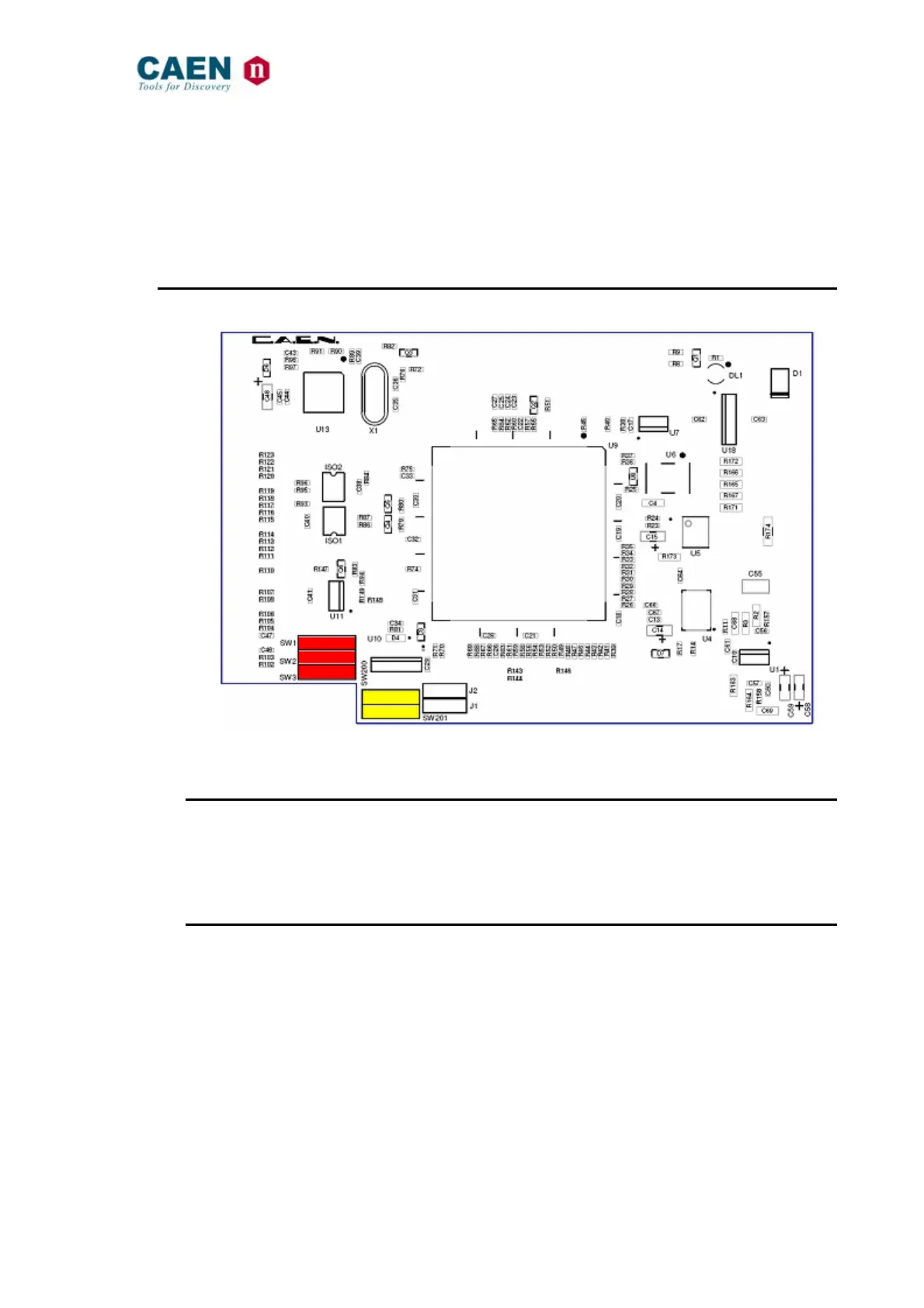
4.2. Internal switches
Fig. 4.2: Dip switch position
4.2.1. Local Bus termination
The SW[1..3] switch placed on the Microcontroller board inside the module (behind the
Remote communication control section, see § 2.4.4), allows to terminate the Local Bus
for daisy chain purposes (see § 3.4.1.2); dot NOT visible = Termination ON.
4.2.2. RS485 – RS232 conversion
The SW[200, 201] switch placed on the Microcontroller board inside the module, allows
to adapt RS485 signals to RS232; dot visible = Adaptation ON.