PRELIMINARY
Document type: Title: Revision date: Revision:
User's Manual (MUT) N1471 4 Channel Programmable HV Power Supply 24/03/2010 1
NPO: Filename: Number of pages: Page:
00112/07:N1471.MUTx/01 N1471_REV1.DOC 38 13
Table 2.2: Interlock operation
CONFIGURATION ↓ INTERLOCK MODE (§ 3.1.1) →
OPEN CLOSE
leave contact open INTERLOCK ENABLED
voltage level (0÷1V, ~5mA current) between pin 2 and pin 3 INTERLOCK ENABLED
short circuit pin 1 with pin 2, and pin 3 with pin 4 ENABLED INTERLOCK
voltage level (4÷6V, ~5mA current) between pin 2 and pin 3 ENABLED INTERLOCK
The front panel Interlock LED is ON when the INTERLOCK is enabled; as INTERLOCK
is enabled, channels are turned off
at the fastest available rate, regardless the RAMP
DOWN setting.
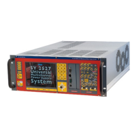
2.4.4. Remote communication control section
Fig. 2.8: Remote communication control and RS485 I/O – RS232 IN electrical scheme
NAME: TYPE: FUNCTION:
IN AMP 280371-2
RS485 Input
2
; adaptable to RS232 standard (see also § 4.2.2)
OUT AMP 280371-2
RS485 Output
USB B TYPE USB
USB2.0 compliant realized via USB ↔ RS232 FT232BM converter
2
RS 485 Serial Port Interface allows to control up to 32 modules connected by a twisted pair cable; the first and
last modules must be terminated, see § 4.2.