PRELIMINARY
Document type: Title: Revision date: Revision:
User's Manual (MUT) N1471 4 Channel Programmable HV Power Supply 24/03/2010 1
NPO: Filename: Number of pages: Page:
00112/07:N1471.MUTx/01 N1471_REV1.DOC 38 12
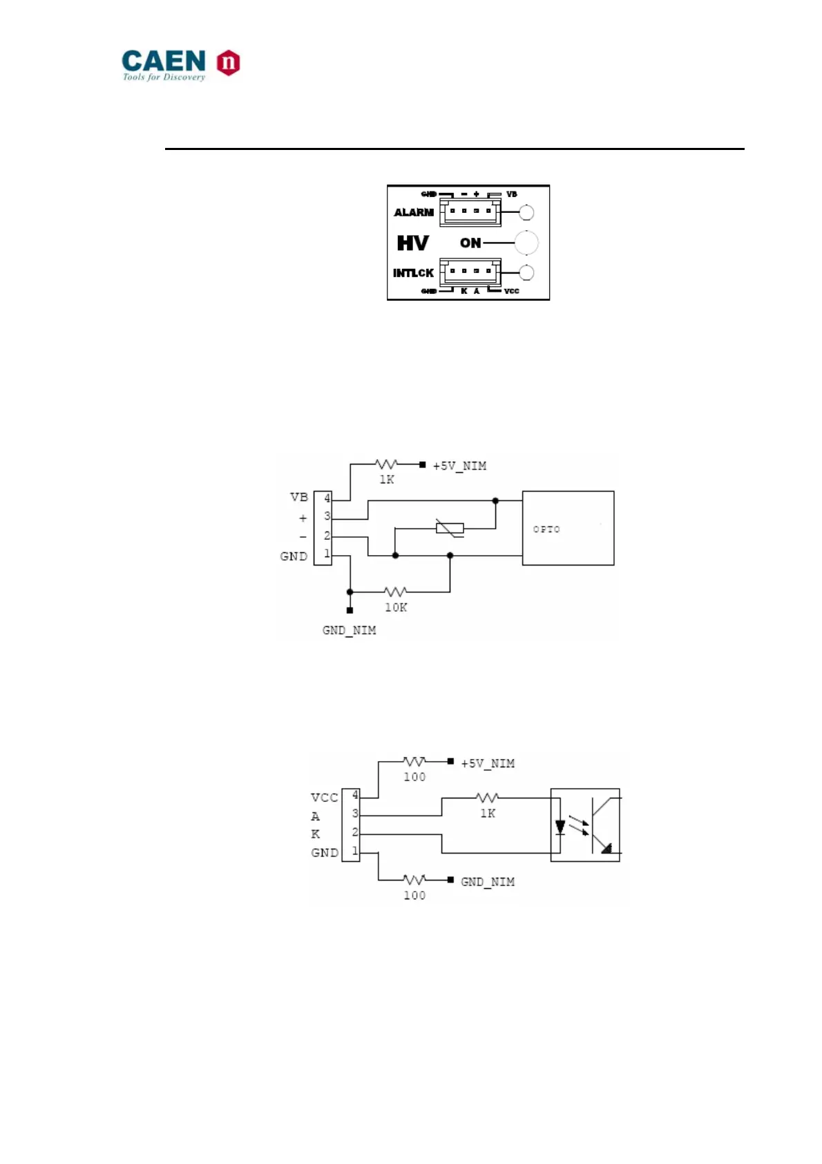
2.4.3. HV Status control section
Fig. 2.5: N1471 HV Status control panel
NAME: TYPE: SIGNAL: FUNCTION:
ON RED LED
HV On enabled (at least one channel ON)
ALARM RED LED/LEMO CONN. Out
Alarm status signaled (active LOW)
INTERLOCK RED LED/LEMO CONN. In
Interlock signal
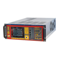
2.4.3.1. Alarm signal
Fig. 2.6: N1471 ALARM electrical scheme
Alarm signal output signal electrical scheme is reported in the figure above. The
maximum output is 400mA@12V on ± Pins.
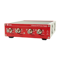
2.4.3.2. Interlock signal
Fig. 2.7: N1471 INTERLOCK electrical scheme
A schematic diagram of the Interlock input is shown in the figure above, where the diode
is part of optocoupler stage.
Interlock means that channels are hardware disabled. The interlock operation is
explained by the following table: