PRELIMINARY
Document type: Title: Revision date: Revision:
User's Manual (MUT) N1471 4 Channel Programmable HV Power Supply 24/03/2010 1
NPO: Filename: Number of pages: Page:
00112/07:N1471.MUTx/01 N1471_REV1.DOC 38 11
2.4. Front panel connections
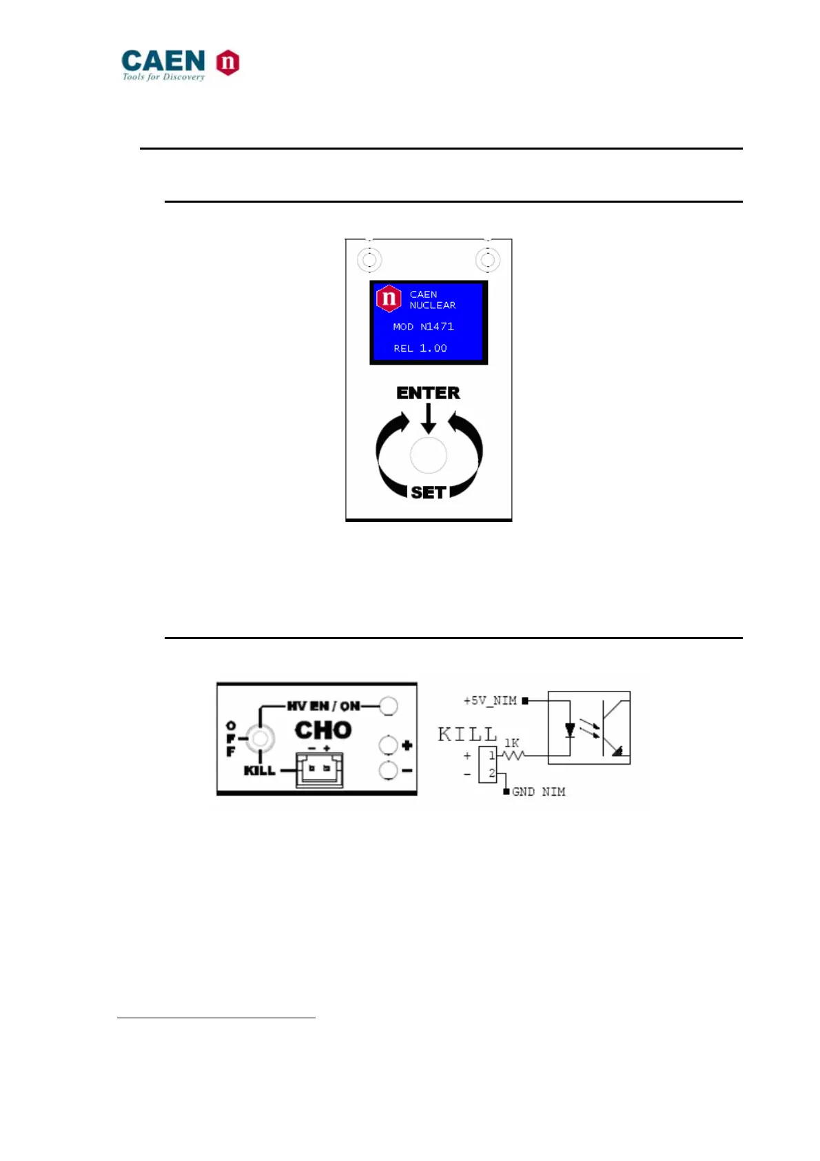
2.4.1. Local control section
Fig. 2.3: Local control panel
NAME: TYPE: FUNCTION:
MONITOR
1” OLED DISPLAY (96x64)
Local settings monitoring
TUNE
ROTARY SWITCH
Parameter and Mode setting
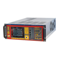
2.4.2. Channel control section
Fig. 2.4: Channel control panel and Kill scheme
NAME: TYPE: FUNCTION:
HV_EN/OFF/KILL 3 POS. SWITCH
Channel Enable and turning OFF/KILL
1
ON RED LED
HV On enabled
REMOTE KILL
AMP 280370-2
The channel is KILLED as no current flows across the
1Kohm resistor; this is achieved either as the 1-2 contacts
are open or as a +4÷6Vdc voltage is fed to pin 1 (see note)
+ GREEN LED
Positive polarity
- YELLOW LED
Negative polarity
1
OFF: Channel turned off according to RAMP DOWN setting; KILL: Channel turned off at fastest available rate