Mod. NIM8304 12 slot 7U(5+2) Switching NIM Crate
4. FAN Tray Section
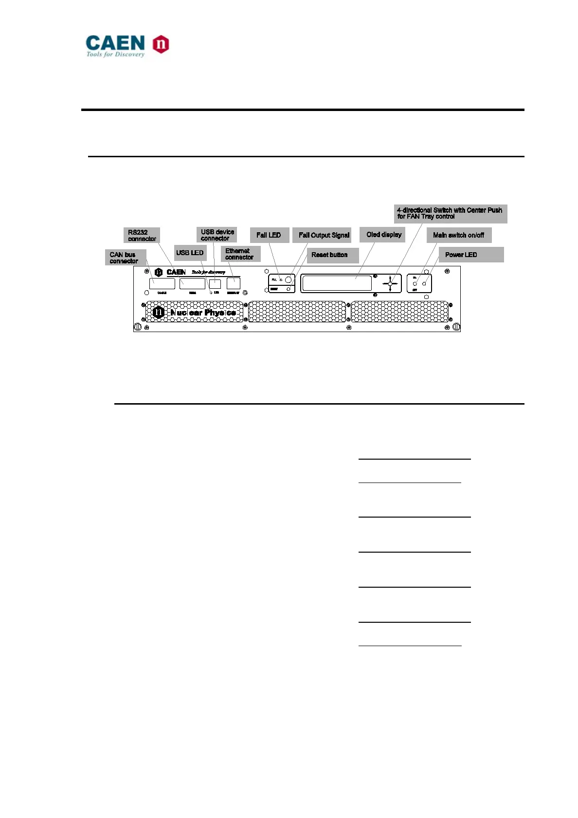
4.1 FAN Tray front panel
Fig. 4.1: Mod. NIM8304 FAN Tray Front view
The Fan Tray housed a buzzer for Alarm signaling.
4.1.1 Fan tray Front panel connectors
The location of the connectors is shown in Fig. 4.1. Their electromechanical specifications
are listed here below.
USB DEVICE PORT: Mechanical specifications:
USB B female connector
Electrical specifications:
USB 2.0 compliant
RS232 INTERFACE CONNECTOR: Mechanical specifications:
9 pin D type female connector
ETHERNET INTERFACE CONNECTOR: Mechanical specifications:
10Base-T female connector (RJ 145)
CAN BUS INTERFACE CONNECTOR: Mechanical specifications:
9 pin D type male connector
FAIL Output Connector: Mechanical specifications:
LEMO connector
Electrical specifications:
See Fig. 4.5