37
Proprietary Information: Not for use or disclosure except by written agreement with Calix.
© 2001-2009 Calix. All Rights Reserved.
Terminating Fibers
Once SFP transceiver modules are installed in the E5-400 chassis, you can terminate fibers to
the SFPs. Be sure the connector type on the fibers matches the connector type on the SFP
module(s). If the laser at the far end of the fibers is enabled, you can use an optical power
meter to test the signal strength on the fibers before connecting to the equipment. Defer to
local practice wherever applicable.
DANGER! CLASS 1 LASER PRODUCT. INVISIBLE LASER RADIATION
PRESENT. Fiber optic radiation can cause severe eye damage or
blindness. Do not look into the open end of an optical fiber.
To terminate fibers to the E5-400
1. Route the fibers to the equipment.
Important: Because the fan tray module slides out the front of the unit, it is necessary
that any exiting fibers are routed to the left-hand side of the E5-400 chassis.
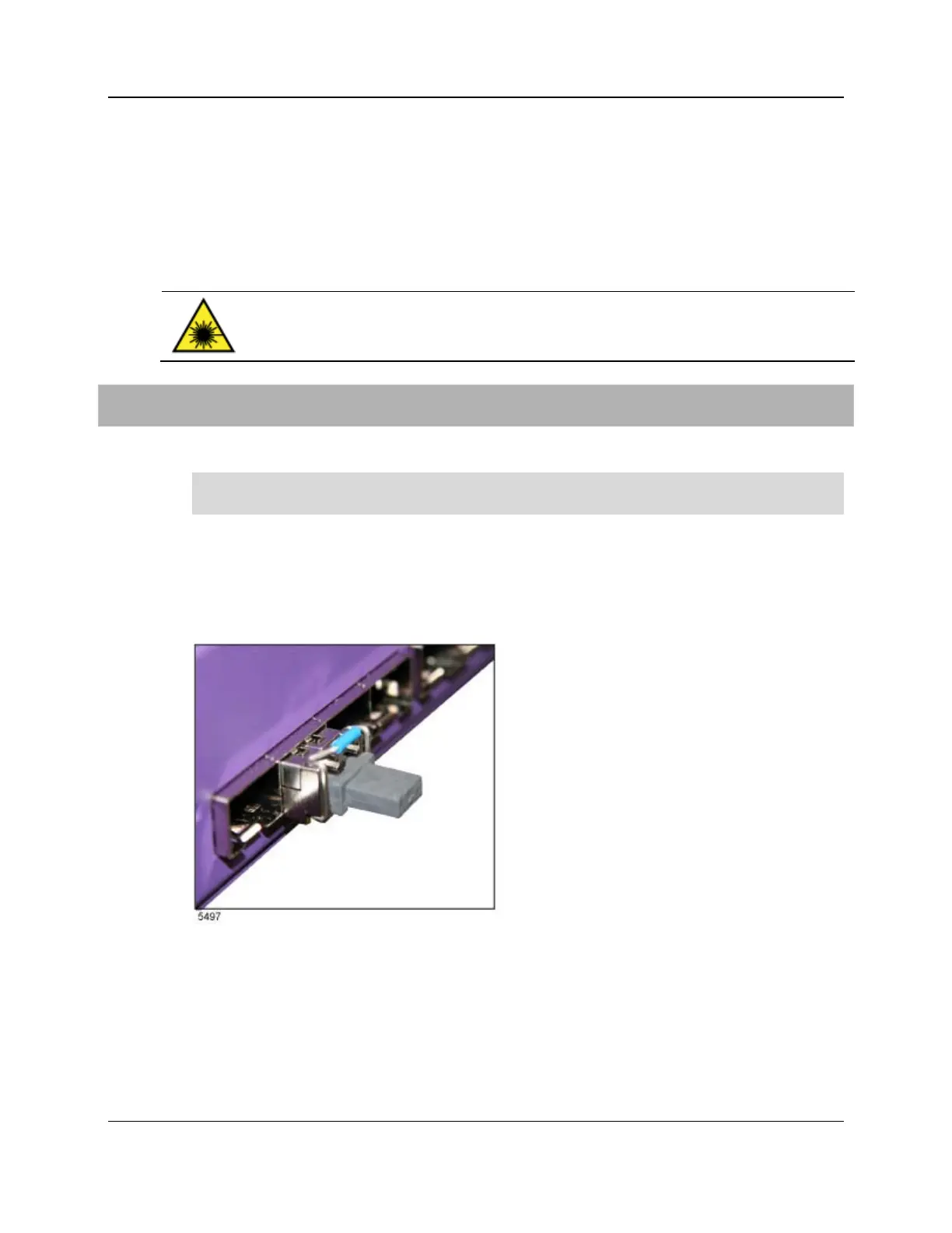
2. Remove the plugs from the optical connectors on the fibers, if present.
3. Remove the protective cap from the transceiver module (installed in the GE or 10GE
port housing).
4. Connect the fibers to the transceiver module.
5. To install additional fiber links, repeat Steps 1 through 4 as required.
6. Neatly coil any slack fiber and dress it so that it will not get pinched or damaged, or
interfere with or become snagged on the equipment.
7. Secure the fibers in place with a suitable strap.