20
Proprietary Information: Not for use or disclosure except by written agreement with Calix.
© 2001-2009 Calix. All Rights Reserved.
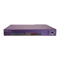
Installing the E5-400 Chassis
Determining the Installation Location
The Calix E5-400 unit is designed as a rack mountable unit.
For rack mounted systems, keep the following in mind:
The E5-400 fan tray is located on the right side of the unit. Adequate airflow on the right
and left (exhaust) sides of the E5-400 is required to properly cool the unit.
SFP, XFP, and SFP+ connectors that are attached to the front of the E5-400 unit must
be secured with strain relief and routed to avoid exceeding the manufacturer's bend
radius standards.
Power, alarm, and ground wiring entering the rear of the E5-400 must be properly
secured with strain relief.
Locate the E5-400 near power and ground connection points.
Note: The power cord and ground cable provided with the E5-400 are 12 feet long.