15
Proprietary Information: Not for use or disclosure except by written agreement with Calix.
© 2001-2009 Calix. All Rights Reserved.
Materials and Tools Checklist
The tools and equipment required to install a Calix E5-400 follow.
Calix-supplied materials
The following materials are provided by Calix and shipped with each E5-400 unit:
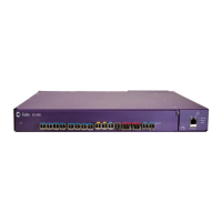
(1) Calix E5-400 unit
(1) Fan tray assembly with captive screw
(4) Self-tapping rack mounting screws, 12-24 x .625-inch
(2 ea.) Mounting ears (19-inch and 23-inch sizes)
(8) Phillips screws, 4-40 x .1875-inch (for attaching mounting ears)
(2) Power cable assemblies, #18 AWG dual (A,B) input, ring terminals, 12-foot length
with 200 Ohm ferrite beads
(1) Ground cable, #8 AWG stranded, 2-hole lugs, 12-foot length
Up to (2) XFP optics modules (ordered and packaged separately)
Up to (2) SFP+ optics modules (ordered and packaged separately)
User-supplied materials
The following materials are required to complete an E5-400 installation, but are not supplied
by Calix:
19- or 23-inch equipment rack
-48 VDC power source with fuse-protected dual power feeds (5 Amp GMT fuse
positions)
Fuse panel with standard dual power feeds (5 Amp GMT fuse positions)
SFP optics modules (up to 12)*
Ethernet management cable
Fiber cleaning kit (e.g., rubbing alcohol, cotton swabs, compressed air)
Labels for identifying specific port wiring
Oxidation prevention grease for ground wire connection
*Note: All SFPs must be Class 1 laser devices in accordance with FDA regulation 21CFR
1040.10, 1040.11, and IEC 60825-1.