33
Proprietary Information: Not for use or disclosure except by written agreement with Calix.
© 2001-2009 Calix. All Rights Reserved.
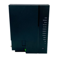
Wiring the Alarm Interfaces
The rear panel of the E5-400 includes a removable access cover where power, ground, and
the alarm interface are housed. This section describes how to wire external environmental
alarms and audible and visual alarms. See the Calix E5-400 User Guide for descriptions of the
available alarms.
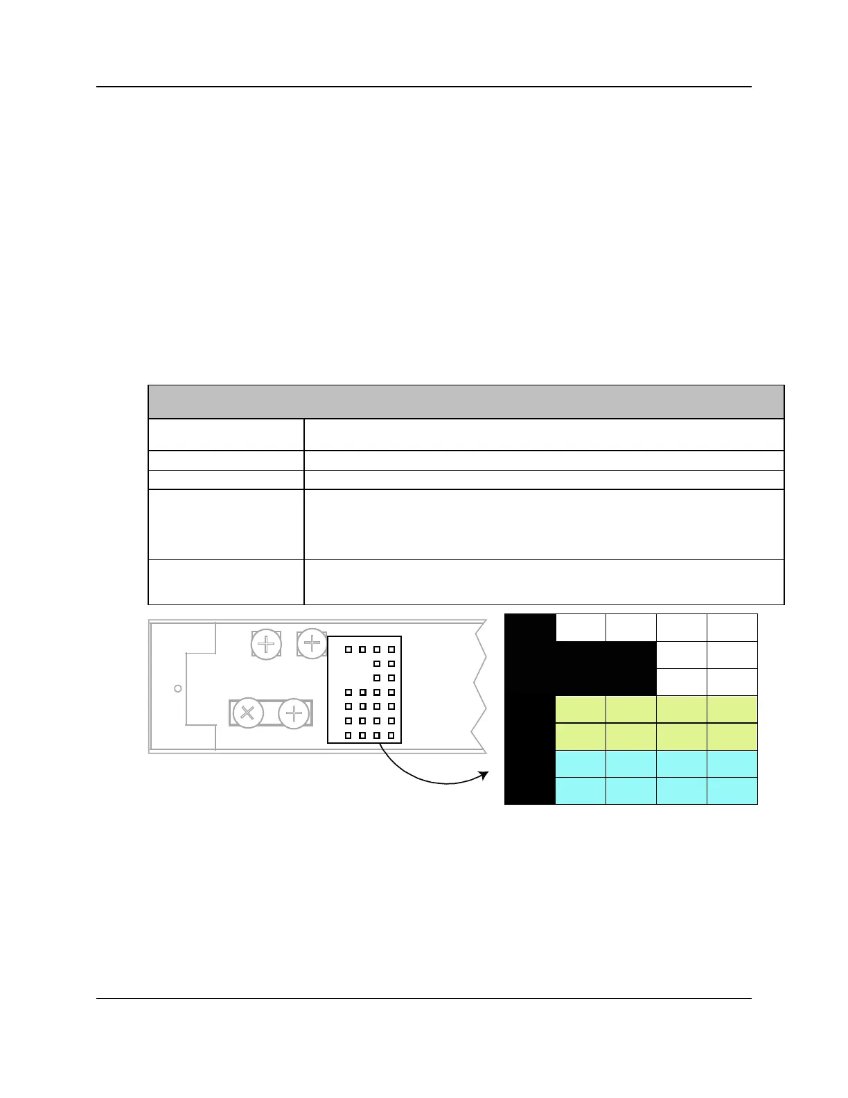
Wiring Environmental Alarms
The E5-400 alarm interface is located on the rear of the E5-400 unit immediately to the right
of the ground bus bar.
Definitions of each alarm pin pair are included below:
Alarm Pin Definitions
CUTX, CUTR Craft UART Interface, Transmit and Receive. Allows for a permanent Craft Interface
Connection on the back of the E5-400.
LGND, LGND Low Voltage Ground Pins
ETX, ETR (+ and -) Ethernet Management Pins, Transmit and Receive
AL0 - AL3 (+ and -) Configurable as input/out alarm circuits. These normally open alarm pins can be configured to
interface with various alarm management devices such as sirens or horns located in the central
office or remote locations. ALM0 through ALM2 default to Critical, Major, and Minor Alarm
Severity, respectively. ALM3 is not configured by default but can be configured as an input or
output pair with the desired severity level.
AL4 - AL7 (+ and -) These input only pins are tied to Battery_RTN (+) and -48 VDC (-). These pin pairs detect
contact closure only and will raise an alarm. Refer to the E5-400 User Guide for information on
alarm provisioning and supported hardware or environmental alarms.
AL4-
AL4+
AL0-
AL0+
AL1-
AL1+
AL5-
AL5+
AL2-
AL2+
AL6-
AL6+
AL3-
AL3+
AL7-
AL7+
ATAP
ATAN
BTAP
BTAN
ETX+
ETX-
ERX+
ERX-
CUTX CUTR LGND LGND
5461