25
Proprietary Information: Not for use or disclosure except by written agreement with Calix.
© 2001-2009 Calix. All Rights Reserved.
Testing the Power Supply Levels
If power level readings fall outside the ranges given below, troubleshoot the wiring and
measure the power at the source end before continuing with the installation process.
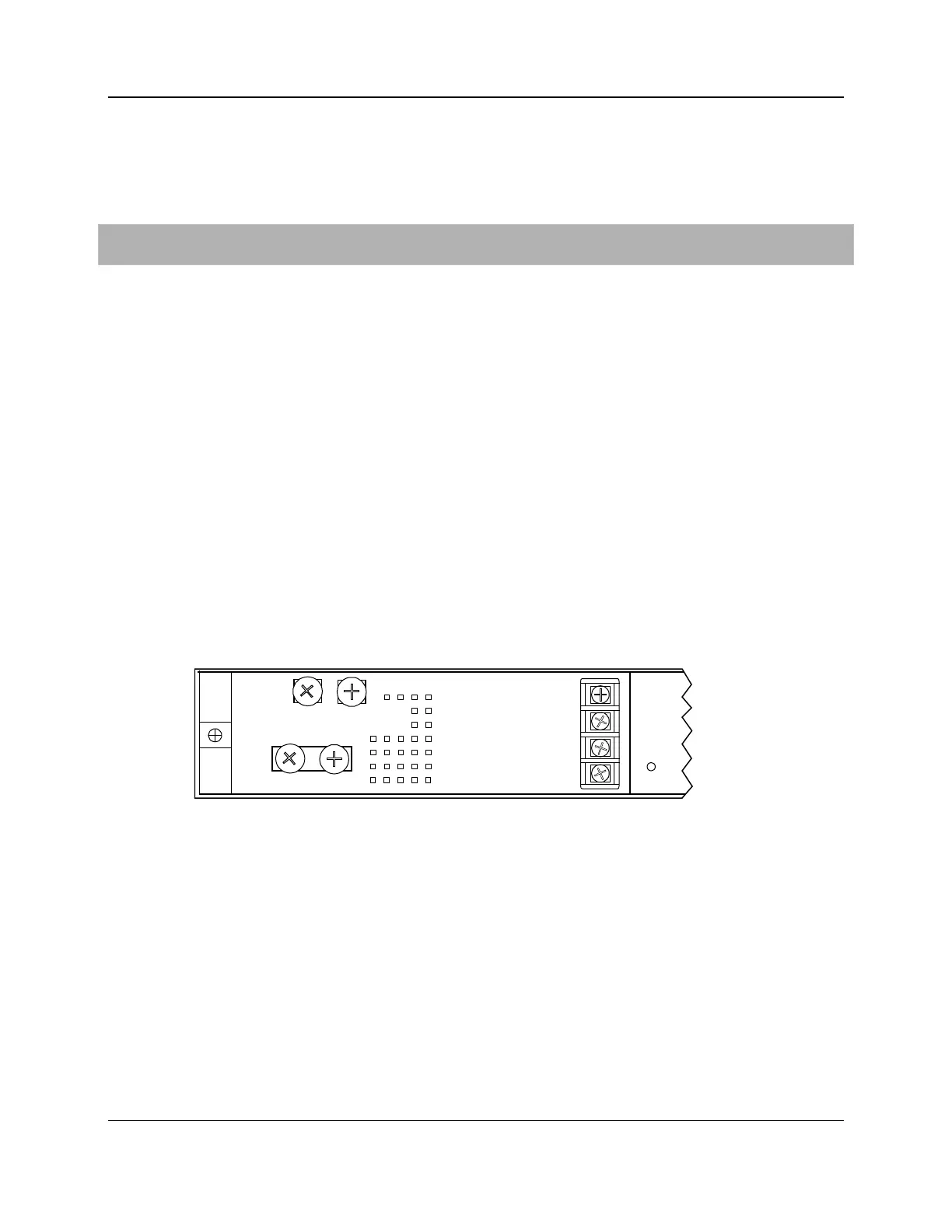
To test power to the E5-400
1. Verify that the –48 VDC power supply is "on" at the source.
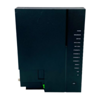
2. Using a digital volt meter, test the input power at the E5-400 power terminals located on
the rear panel:
a. Place the volt meter positive lead on the A-side negative (-48V A) terminal lug.
b. Place the volt meter negative lead on the rack frame ground.
c. Verify that the voltage measures between –48 to –60 VDC.
d. Repeat steps 2a-2c for the B-side negative (-48V B) terminal, if equipped with power.
e. Place the volt meter positive lead on the A-side positive (-48V RTN A) terminal lug.
f. Place the volt meter negative lead on the rack frame ground.
g. Verify that the volt meter measures 1 volt or less.
h. Repeat steps 2e-2g for the B-side positive (-48V RTN B) terminal lug.
3. If the readings are outside of these ranges, check for connection integrity and fuse or
breaker conditions as applicable, and retest the voltage.
-48V RTN A
-48V A
-48V RTN B
-48V B
5558