30
Proprietary Information: Not for use or disclosure except by written agreement with Calix.
© 2001-2009 Calix. All Rights Reserved.
Wiring the Out-of-Band Management Interfaces
This section describes how to wire the E5-400 out-of-band management interfaces, including
connecting to the front Ethernet management port (RJ-45), and wiring out the rear Ethernet
management port and RS-232 serial port (wire-wrap pins).
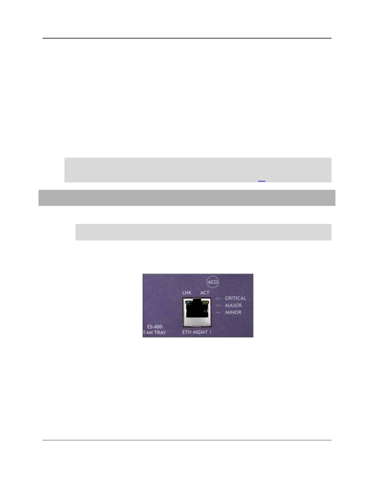
Connecting to the Front Ethernet Management Port
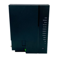
The E5-400 front panel is equipped with a 10/100 Fast Ethernet management port (RJ-45
connector), located on the fan tray module. Use a straight-through Ethernet jumper cable to
connect your PC to the Ethernet management port.
Note: If you require permanent out-of-band management connectivity to the E5-400, Calix
recommends connecting to the rear Ethernet management port (wire-wrap pins located on
the rear panel). See Wiring the Rear Ethernet Management Port (on page 31) for instructions.
To connect to the front Ethernet management port
1. Locate a straight-through Ethernet cable with RJ-45 connectors on both ends.
Note: The E5-400 front Ethernet management port auto-senses transmit and receive
signals. Use either a straight-through or cross-over cable to connect to the Ethernet port.
2. Connect one cable end to the E5-400 Ethernet management port, located on the front
panel (labeled ETH MGMT 1).
3. Connect the other cable end to the Ethernet port on your PC.