Do you have a question about the Calix E5-400 and is the answer not in the manual?
Specifies the target users for this installation guide, including engineers and technicians.
Lists other Calix documentation sets relevant to the E5-400 product.
Explains the meaning of DANGER, WARNING, CAUTION, ALERT, and LASER safety notices used in the document.
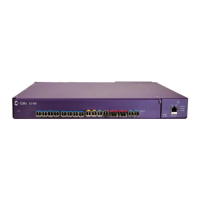
Provides an introduction to the Calix E5-400 Ethernet transport and aggregation platform.
Details the interfaces and components located on the rear panel of the E5-400 unit.
Presents detailed exterior dimensions for the Calix E5-400 chassis and fan tray module.
Provides general guidelines and practices to follow before starting installation activities.
Lists critical safety precautions and warnings for personnel performing installation.
Outlines the high-level steps involved in installing the Calix E5-400 unit.
Details the Calix-supplied and user-supplied materials and tools required for installation.
Lists the necessary tools and optional test equipment required for the E5-400 installation.
Specifies the necessary site conditions and prerequisites for installing the E5-400.
Provides guidance on selecting an appropriate location for rack-mounting the E5-400 unit.
Explains how to attach the correct mounting ears to the E5-400 for rack installation.
Details the process of securing the E5-400 chassis into the equipment rack.
Describes the procedure for properly grounding the E5-400 chassis to the Common Bonding Network.
Provides instructions for connecting the -48 VDC power supply to the E5-400 unit.
Explains how to verify the input DC power levels using a digital voltmeter.
Details how to insert and secure the replaceable fan tray filter into the fan tray module.
Provides steps for removing and installing a new fan tray module.
Connects a PC to the front panel's 10/100 Fast Ethernet management port.
Wires the rear Ethernet management port using wire-wrap pins for out-of-band access.
Explains wiring the RS-232 serial port for a PC console connection.
Connects external environmental alarms to the E5-400 unit's rear panel.
Wires audible and visual alarms to the E5-400's alarm contacts.
Installs SFP, SFP+, and XFP transceiver modules into the E5-400 Ethernet ports.
Details installing and removing mini GBIC transceiver modules from the E5-400.
Connects and secures fiber optic cables to transceiver modules.
Describes the procedure for cleaning or replacing the fan tray filter.
Provides steps for removing and installing a new fan tray module.
Presents a table of system specifications for the Calix E5-400.
Provides guidance on proper techniques for handling and splicing fiber optic cables.
| Model | E5-400 |
|---|---|
| Type | Network Router |
| Max Throughput | 4 Gbps |
| Wireless | No |
| Operating Temperature | 0°C to 40°C |
| Storage Temperature | -20°C to 70°C |
| Management | SNMP |
| Ports | 4 x 10/100/1000 Mbps Ethernet |
| Humidity | 5% to 95% non-condensing |