GB
MXV, MXV-B Rev4 - Operating Instructions Page 21 / 136
8.2. Dismantling the system
Close the suction and delivery gate valves and drain
the pump casing before dismantling the pump.
8.3. Dismantling the pump
OFF
Before dismantling, close the gate valves in the suction
and delivery pipes and empty the pump casing (g. 4).
For dismantling and re-assembly refer to the section
drawing (section 14.) and gures 5, 6.
Dismantling and inspection of all internal parts can be
carried out without removing the pump casing (14.00)
from the pipeline.
Sequence for dismantling MXV-B:
By removing the nuts (61.04) from the tiebolts (61.02)
the motor can be taken out complete (99.00), with all
internal parts of the pump without removing the pump
casing (external jacket 14.02) from the pipeline.
Sequence for dismantling MXV(L), MXV(L)4:
1. Mark the position of the motor on the lantern bracket
(32.00), and the position of the lantern bracket on
the upper cover (34.02), ... on the external jacket
(14.02), ... on the pump casing (14.00).
2. Remove the screw (32.32) with the washer (32.31)
and the coupling guard (32.30).
3. Loosen the screws (64.25) of the coupling (64.22).
ATTENTION: to avoid compressing the spring of the
mechanical seal (36.00) because of axial shifting
of the shaft (64.00), we recommend to loosen the
screws (64.25) of the coupling (64.22) even only for
removing or replacing the motor.
Afterward reposition the shaft (64.00) as indicated in
section 9.2.
4. Disconnect the power cable from the terminal box,
remove the screws (70.18) with the nuts (70.19) and
remove the motor away from the coupling (64.22)
(g.5a).
For MXV(L) 25-32-40, MXV(L)4 25-32-40:
5. Remove the nuts (61.04) from the tiebolts (61.02).
6. Remove the lantern bracket (32.00), complete with
bearing (66.00) and coupling (64.22) from the shaft
(64.00) and from the external jacket (14.02).
Once the lantern bracket (32.00) has been removed,
all the internal parts can be extracted with the shaft
(64.00) from the external jacket (14.02).
7. Remove the upper cover (34.02) with the o-ring
(14.20) and then the delivery casing (20.00).
For MXV(L) 50-65-80, MXV(L)4 50-65-80:
5. Remove the screws (61.07) and remove the lantern
bracket (32.00), complete with bearing (66.00) and
coupling (64.22) from the upper cover (34.02) and
from the shaft (64.00) (g.5a).
6. Remove the nuts (61.04) and washers (61.03) from
the tiebolts (61.02).
7. Remove the upper cover (34.02) from the shaft
(64.00) and from the external jacket (14.02) - or with
the external jacket from the pump casing (14.00) -
with the aid of a mallet or lever, exercising pressure
in alternate operations, from diametrically opposite
positions.
Once the upper cover (34.02) has been removed,
all the internal parts can be extracted from the pump
casing (14.00).
8.4. Replacing the mechanical seal
Make sure the spring of the new mechanical seal is
set with the direction of the winding suitable for the
direction of rotation of the shaft.
Make sure that all parts with which the mechanical seal
comes into contact are perfectly clean and free from
any burr or cutting edges.
The seal rings in EPDM (Ethylene-Propylene) must
never come into contact with oil or grease. To
facilitate the mounting of the mechanical seal, lubricate
the shaft, the seating of the stationary part and the seal
rings with clean water or any other lubricant compatible
with the material in which the seal rings are made.
Use every precaution so as not to damage the seal
surfaces with blows or angular impact.
Only for MXV(L)(4) 25,32,40,50,65,80
Remove the mechanical seal (36.00), the rotating
part from the shaft (64.00), making sure the shaft is
not scratched, and then the xed part from the upper
cover (34.02).
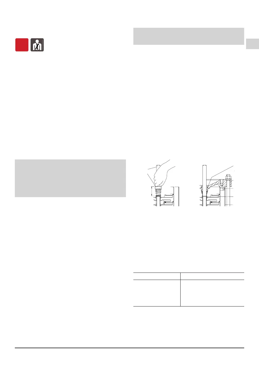
Push the rotating part as far as the shoulder ring
(36.52) on the shaft (64.00), without compressing the
spring. Check the length before and after insertion and
raise the rotating ring as far as the initial length (L1 in
g.5).
In this way, correct compression of the spring will be
ensured when the xed part is mounted and after the
shaft is locked in the coupling (L2 in g.6b).
64.00
36.00
Parte
14.20
14.02
36.52
34.02
(*)
64.22
64.25
Fig.5 Montaggio tenuta meccanica
Fig. 6b
Rotore sollevato,
posizione di
bloccaggio
albero nel giunto
sollevamento albero
nel giunto. (*) Spina per
albero non bloccato
Rotore appoggiato
Fig. 6a
L1
L2
rotante
fissa
Parte
36.00
64.00
4.93.226/2
4.93.226/1
Fig.5 Inserting the mechanical seal
Only for MXV(L) 100, MXV(L)4 100 (see section 16.
page. 131)
8.5. Replacing the ball bearing MXV(L), MXV(L)4
If the ball bearing (66.00) has to be replaced, use a
2RS1 C3-type, of the size marked on the ball bearing
to be replaced and containing grease lubricant suitable
for the operating temperature.
The size of the bearing depends on the size of the
motor:
motor size ball bearing
80 6206, 2RS1, C3
90 6207, 2RS1, C3
100-112 6208, 2RS1, C3
132 6310, 2RS1, C3
160-180 6313, 2RS1, C3
8.6.
First-stage bearing and intermediate bearing
The MXV 50-16, 65-32 and 80-48 pumps have a
bearing sleeve (64.10) on the shaft (64.00) and a
bearing in the stage casing (25.03) behind the rst
impeller (according to the order of suction).
Starting with the MXV.. 25-212, MXV.. 32-412 e MXV..
40-811, MXV 50-1611, MXV 65-3208 and MXV 80-
Rotating
part
Fixed
part
 Loading...