GB
Page 24 / 136 MXV, MXV-B Rev4 - Operating Instructions
Electric motor Calpeda
M.. V1
OPERATING INSTRUCTIONS
Table of contents
Subject Page
1. Example plate motor .....................................................24
2. Lifting .............................................................................24
3. Installation and starting .................................................24
4. Operation conditions .....................................................24
5. Motors working at variable speed..................................25
6 Maintenance ..................................................................25
7. Servicing ........................................................................25
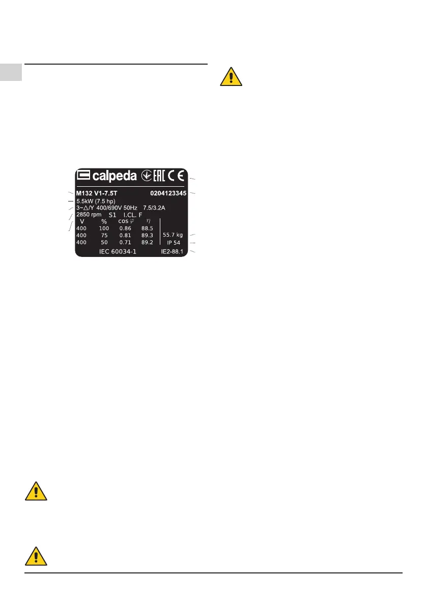
1. Example plate motor
Example plate motor 50Hz
Made in Italy
MONTORSOVICENZA
Made in Italy
MONTORSOVICENZA
1
2
3,4,5
6,7,8
1,12
1 Type
2 Nominal power
3 Power voltage
4 Frequency
5 Current
6 Nominal speed
7 Service type
8 Insul. class
9 Voltage
10 % load
11 cos f
12 yield
13 Certications
14 Serial number
15 Weight
16 Protection
17 Efciency rating
2. Lifting
All CALPEDA motors that weigh more than 25 kg are equipped
with lifting eyebolts.
Only the main lifting eyebolts must be used to lift the motor,
but they must not be used when the motor is connected to the
pump. The centre of balance of motors with the same axis
height can vary according to the different powers, the assembly
layout and the auxiliary equipment. Damaged eyebolts must
not be used. Make sure the eyebolts are not damaged before
lifting the motor.
The lifting eyebolts must be shut before being used.
Make sure suitable lifting equipment is used, and that the
lifting hook size is adequate for the eyebolts. Be careful not
to damage the auxiliary equipment and the cables connected
to the motor.
3. Installation and starting
Disconnect the motor before working on it or on the
equipment it moves.
3.1 Insulation resistance check
Check insulation resistance before starting the machine and
when you suspect that humidity is forming in the windings.
Disconnect the motor before working on it or on the
equipment it moves.
Insulation resistance, correct at 25°, must exceed the reference
value of 100 MΩ (measured at 500 VDC). The insulation
resistance value halves every time the room temperature
increases by 20 °C.
The motor casing must be earthed and the windings
must be discharged immediately after measuring to
prevent risks of electric shock.
Windings soaked in sea water usually need to be redone.
3.2 Motor tting and alignment
Make sure there is enough space around the motor to guarantee
air circulation. Correct alignment is essential for preventing
bearing faults, vibrations and possible shaft breakage.
Align the motor using suitable methods. Re-check alignment
after tightening the bolts or stud bolts for the last time.
Do not exceed the load values permitted for the bearings,
which are given in the product catalogues.
3.3 Machines with condensate discharge tap
Make sure the discharge holes and taps are turned downwards.
All the discharge holes must be closed in dusty areas.
3.4 Wiring and electrical connections
The terminal box of standard single speed motors normally
contains 6 winding terminals and at least one earth terminal.
In addition to these, the terminal box can also contain the
thermistor connections, anti-condensation resistors, or other
auxiliary devices.
Suitable cable terminals must be used for connecting. The
auxiliary device cables must be connected directly to the
relative terminals. The machines cannot be moved once
they have been positioned. Unless otherwise indicated, the
cable input threads are expressed in metric units. The cable
glands must have the same protection level and IP rating as the
terminal boxes. With cable inputs, use cable glands and seals
that are compliant with the protection type and the type and
diameter of the cable.
Earthing must be carried out in compliance with local laws
before connecting the motor to the mains.
Make sure the protection level of the motor is suitable for the
environmental and climatic conditions; for example make sure
water cannot enter the motor or the terminal boxes.
The terminal box seals must be inserted correctly into their
respective seats to guarantee the correct IP rating.
3.4.1 Connection for different starting methods
The terminal box of standard single speed motors normally
holds six winding terminals and at least one earth terminal,
which allow DOL or Y/D starting. Refer to the Figure.
1 .Wiring drawing (only for Calpeda motors)
4. Operation conditions
4.1 Use
Unless indicated otherwise on the nominal data plate, the
motors are designed for the following environmental conditions.
- Maximum surrounding temperature from -20°C to +40°C.
- Maximum altitude 1,000 m above sea level.
- Power supply tolerance ±5% and frequency ±2% in
compliance with EN / IEC 60034-1.
The motor can only be used for the applications it has been
designed for. The nominal values and operation conditions are
 Loading...