5
1
7
2
8
7
7
6
5
6
9
5
5
4
3
p. 7 - Manual FA01054-EN - 01/2018 - © CAME S.p.A. -
Translation of the original instructions
When operating at 230 V and outdoors, use H05RN-F-type cables that are 60245 IEC 57 (IEC) compliant; whereas indoors,
use H05VV-F-type cables that are 60227 IEC 53 (IEC) compliant. For power supplies up to 48 V, you can use FROR 20-22 II-type
cables that comply with EN 50267-2-1 (CEI).
To connect the antenna, use the RG58 (we suggest up to 5 m).
If cable lengths differ from those specified in the table, establish the cable sections depending on the actual power draw of
the connected devices and according to the provisions of regulation CEI EN 60204-1.
For multiple, sequential loads along the same line, the dimensions on the table need to be recalculated according to
the actual power draw and distances. For connecting products that are not contemplated in this manual, see the literature
accompanying said products
Cable type and minimum thicknesses
Connection
cable length
< 20 m 20 < 30 m
Control panel power-supply 3G x 1.5 mm
2
3G x 2.5 mm
2
24 V DC gearmotor 3 x 1.5 mm
2
3 x 2.5 mm
2
Flashing light 2 x 0.5 mm
2
Command and control devices 2 x 0.5 mm
2
TX Photocells 2 x 0.5 mm
2
RX photocells 4 x 0.5 mm
2
GENERAL INSTALLATION INDICATIONS
Standard installation
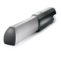
1. Operator
2. Gear motor
3. Flashing light
4. Key-switch selector
5. Photocells
6. Photocells post
7. Mechanical gate stop
8. Junction pit
9. Transmitter