COPYRIGHT © 1999 CANON INC. CANON DADF-B1 REV.0 APR. 1999 PRINTED IN JAPAN (IMPRIME AU JAPON)
2-21
CHAPTER 2 BASIC OPERATION
2. Controlling the Feed Motor (M2)
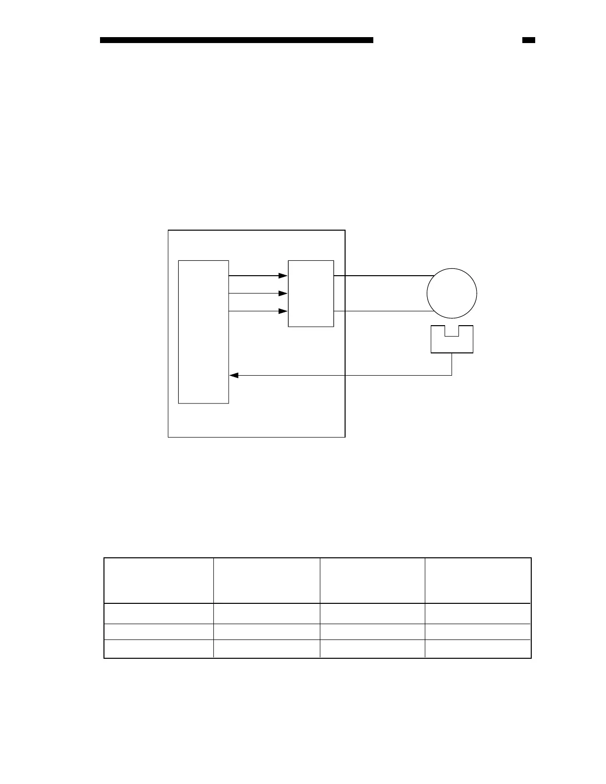
Figure 2-225 is a diagram of the control circuit used for the feed motor (M2).
The feed motor is a DC motor. The CPU (Q1) on the ADF controller PCB sends the feed motor
rotation speed control signal (FMPWM) and the feed motor rotation direction signal (FMFWD,
FMREV) to the drive circuit, which in response drives the feed motor.
When the feed motor (M1) starts to rotate, the feed motor clock sensor (SR1) turns on to send the
feed motor lock signal (FMCK) to the CPU (Q1). In response, the CPU (Q1) compares the rotation
speed that has been selected in advance and the feed motor clock signals (FMCK), and varies the
feed motor rotation speed control signal (FMPWM) to enable the selected speed.
The relationship between the feed motor rotation speed control signal (FMPWM), feed motor
rotation direction signal (FMFWD, FMREV), and feed motor is as follows:
Q1
SR1
CPU
M2
FMPWM J5F-3
J5F-4
FMFWD
FMREV
FMCK
Drive
circuit
ADF controller PCB
Feed motor
Feed motor clock
sensor
Figure 2-226
Stops
Rotates CW
Rotates CCW
’0’
’1’
’0’
’0’
’0’
’1’
’0’
’1’
’1’
Feed motor rotation
speed control signal
(FMPWM)
Feed motor rotation
direction signal
(FMFWD)
Feed motor rotation
direction signal
(FMREV)
Feed motor operation
Table 2-205
 Loading...