13
ENG
“UE BASIC” +03U0042EN - rel. 1.3 - 10 May 2013
3. STEAM DISTRIBUTION
3.1 CAREL jet distributors (SDPOEM00**)
These can be fi tted horizontally or vertically (hole facing upwards).
See page 31 for the models of distributors.
Assembly instructions (see Fig.3.a):
• make a series of holes on the wall according to the distributor drilling
template;
• insert the distributor;
• fasten the fl ange using 4 screws.
31,5 (1.2”)
50 (1.9”)
57,5(2.3”)
100 (3.9”)
C
C
A
B
A
B
50 (1.9”)
50 (1.9”)
31,5 (1.2”)
31,5 (1.2”)
31,5 (1.2”)
56(2.2”)
5(0.2”)
30 (1.2”)
22 (0.9”)
8(0.3”)
30 (1.2”)
22 (0.9”)
8(0.3”)
D
Fig. 3.a
Key:
A.
steam inlet
B.
condensate drain
C.
steam outlet.
the dimensions of the hole vary depending on the models of
distributor:
model SDPOEM0000: hole made manually, up to 30 mm (1.2”) in
diameter);
D
drilling template
Note: if steam hoses with an inside diameter of 30 mm (1.2”) are
used, remove the 22 mm (0.9”) steam inlet section.
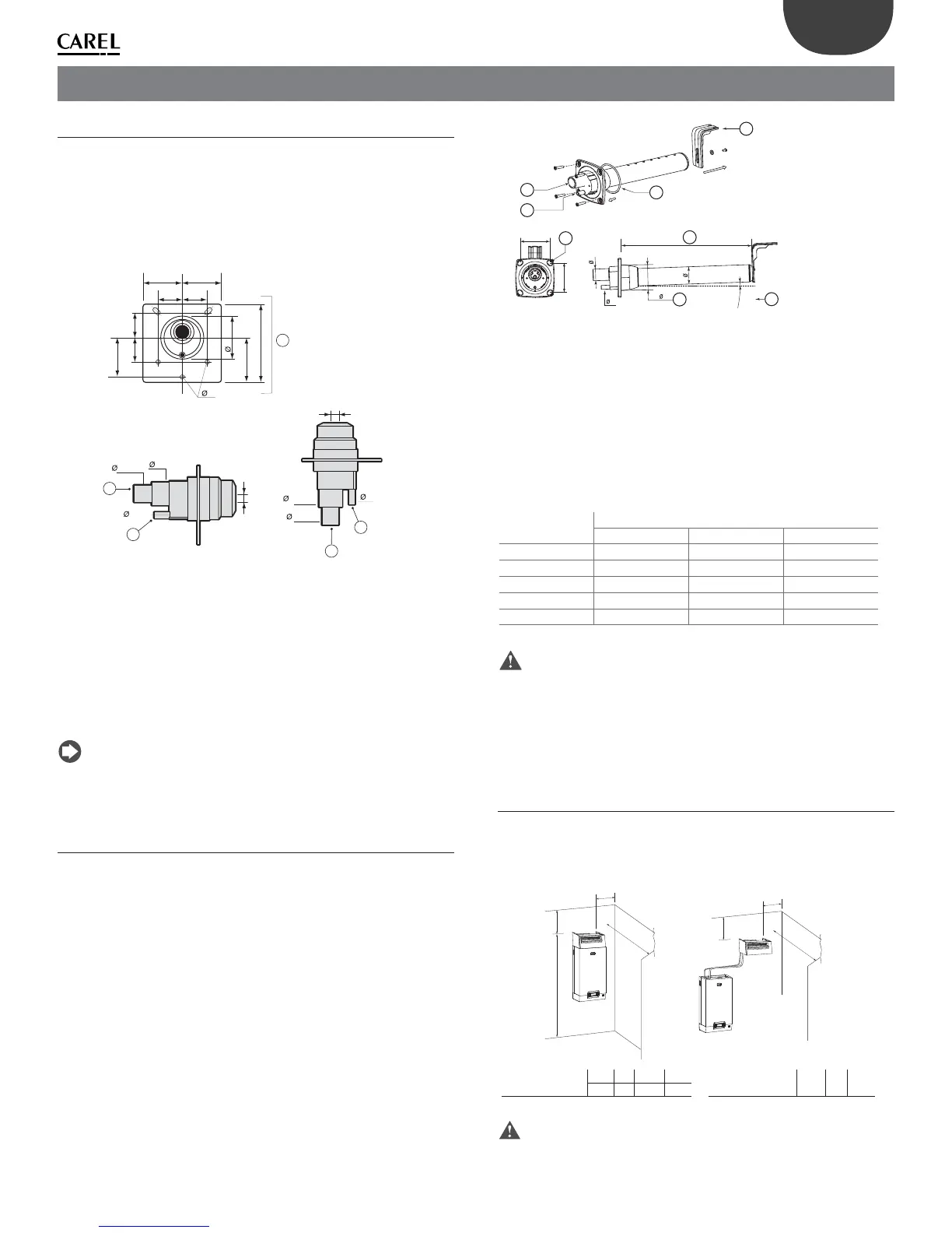
3.2 CAREL linear distributors for air ducts
(DP***DRU)
Install away from obstacles (curves, branches, changes in cross-section, grills,
fi lters, fans).
Minimum distance between the distributor and the obstacle: 1/1.5 m
(3.3/4.9 ft). Increase the distance if:
• the air speed increases in the duct,
• the relative humidity of the air increases before and after humidifi cation,
• the turbulence decreases.
See page 33 for installation examples.
Assembly instructions (see Fig.3.b):
• make a series of holes on the wall according to the distributor drilling
template (included in the packaging with the distributor);
• insert the distributor with the steam holes facing upward;
• fasten the fl ange using 4 screws.
A 22 30 40
B 10 10 10
Y 58 68 89
35 45 60
X 68 77 99
dimensioni in mm
B
Y
X
A
X
°2
1
2
3
4
5
6
8
7
Fig. 3.b
Key:
1
“L”-shaped mounting support (where featured)
2
fl ange gasket
3
steam inlet (ØA)
4
condensate drain (ØB)
5
screw diameter (see the instruction sheet supplied with the distributor)
6
length (depending on the model of distributor, see par. “10.5” page 38)
7
angle (around 2°) for draining the condensate.
8
diameter of the hole on the wall (ØY)
Dimensions in mm (in)
CAREL linear distributors
DP***D22RU DP***D30RU DP***D40RU
ØA
22 (0.9”) 30 (1.18”) 40 (1.57”)
ØB
10 (0.4”) 10 (0.4”) 10 (0.4”)
ØY
58 (2.3”) 68 (2.7”) 89 (3.5”)
Ø
35 (1.4”) 45 (1.8”) 60 (2.4”)
X
68 (2.7”) 77 (3.0”) 99 (3.9”)
Tab. 3.a
Important:
1. fi t the distributor at a slight incline (at least 2°, to prevent the return of
condensate);
2. the “L”-shaped mounting support (see part 1 Fig. 3.c) is supplied with
steam distributor models from DP085* to DP205*. For shorter lengths,
the support can be supplied as an option (code 18C478A088).
3.3 CAREL steam blowers (VSDU0A*, models
UE001 to UE018 only)
Steam distributors for humidifi ers with fl ow rates up to 18 kg/h (39.7 lb/h).
Can be connected on top of the humidifi er, or separately in another location
(see the fi gure below).
A
B
C
D
E
F
G
DIMENSIONS (m) A B C D
>0,5 >5 ≥2,1 >1
DIMENSIONS (m) E F G
>0,5 >5 >1
Fig. 3.c
Important:
For correct distribution of the steam, observe
For correct distribution of the steam, observe the distance
shown in the fi gure above.