7
ENG
“UE BASIC” +03U0042EN - rel. 1.3 - 10 May 2013
1. INTRODUCTION AND ASSEMBLY
1.1 humiSteam basic (UEY*)
Range of isothermal immersed electrode humidifi ers with backlit display for
the control and distribution of steam.
Models available (identifi able from the code shown on the product):
• UE001, UE003, UE005, UE008, UE009, UE010, UE015, UE018 with steam
production capacity up to 18 kg/h (39.7 lb/h), water connections under the
base of the humidifi er;
• UE025, UE035, UE045, UE065 with steam production capacity from 25 to 65 kg/h
(55.1 to 144.3 lb/h), water connections on the side of the humidifi er.
1.2 Dimensions and weights
Models UE001 to UE018 Models UE025 to UE065
B
B
A
C
A
C
Fig. 1.a
UE001 to
UE008
UE009 to
UE018
UE025 to
UE045
UE045** to
UE065
dimensions
mm (“)
A 365 (14.4) 545 (21.5) 635 (25.0)
B 275 (10.8) 375 (14.8) 465 (18.3)
C 712 (28.0) 815 (32.0) 890 (35.0)
weights kg
(lb)
packaged 16 (35.3) 20 (44.0) 39 (86.0) 51 (112.4)
empty 13,5 (29.8) 17 (37.5) 34 (74.9) 44 (97.0)
installed* 19 (41.9) 27 (59.5) 60,5 (133.4) 94 (207.2)
Tab. 1.a
*: in operating conditions, fi lled with water
**: 230 Vac model
1.3 Opening the packaging
make sure the humidifi er is intact upon delivery and immediately notify
the transporter, in writing, of any damage that may be due to careless or
improper transport;
move the humidifi er to the site of installation before removing from the
packaging, grasping the neck only from underneath the base;
open the cardboard box, remove the protective material and remove the
humidifi er, keeping it vertical at all times.
1.4 Positioning
• the unit is designed to be mounted on a wall that is strong enough to
support the weight in normal operating conditions (see Wall-mounting
below). Models UE025 to UE065 can stand on the fl oor;
• to ensure correct steam distribution, position the humidifi er near the point
of steam distribution;
• make sure the humidifi er is level, allowing the minimum clearances (see
Fig. 1.b) for maintenance operations.
Important: during operation the metal casing heats up and the rear
part resting against the wall may reach temperatures in excess of 60 °C
(140 °F) .
Distances from walls
Models UE001 to UE018 Models UE025 to UE065
≥ 500
(16.4”)
<0,5°
≥ 200
(7.9”)
≥ 200
(7.9”)
≥ 200
(7.9”)
≥ 400
(15.7”)
≥ 200
(7.9”)
≥ 200
(7.9”)
≥ 700
(27.6”)
≥ 700
(27.6”)
Fig. 1.b
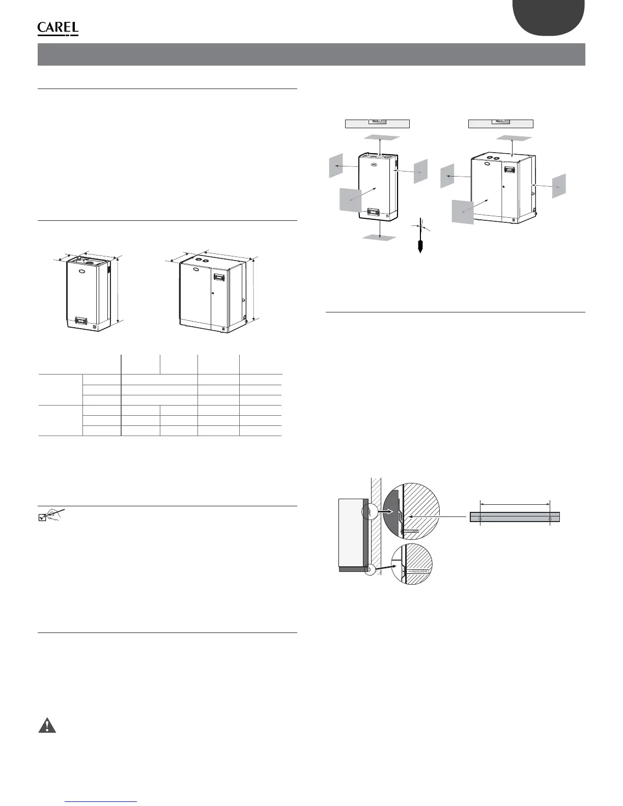
1.5 Wall-mounting
Fit the humidifi er on the wall using the support bracket and the screw kit
supplied (for the dimensions in mm/inches see Fig. 1.d).
Assembly instructions:
1. unscrew the wall bracket from the humidifi er bracket;
2. fasten the wall bracket (see Fig. 1.c), checking horizontal position with a
spirit level; if installed on a masonry wall, the plastic anchor plugs (dia. 8
mm/0.31” ) and screws (dia. 5 mm x L= 50 mm/ 0.19” x L= 1.97” ) supplied
can be used;
3. hang the appliance to the bracket using the slot on the top edge of the
rear of the appliance;
4. secure the appliance to the wall through the hole in the centre on the
rear of the unit. For the weights and dimensions see Tab.1.a.
Models UE001 to UE065
bracket
X
Fig. 1.c