46
ENG
“UE BASIC” +03U0042EN - rel. 1.3 - 10 May 2013
12.5 Automatic insuffi cient supply water
management
The humidifi er checks whether there is no supply water or the fl ow-rate
of supply water is too low, by controlling if the current at the electrodes
increases after opening the fi ll solenoid valve.
In this case, the humidifi er:
• displays alarm “EF”
• activates the alarm relay,
• opens the contactor and closes the fi ll solenoid valve for 10 minutes.
After the 10 minutes, the fi ll solenoid valve is opened, the contactor closed
and the phase current measured: if it increases the alarm is deactivated,
otherwise the procedure is repeated.
NOTE: the alarm is reset automatically and is managed according to the
procedure described above.
12.6 Alarm relay switching
Once the operating hours corresponding to the cylinder maintenance
request have been reached (“CY” alarms), the alarm relay (if there are no
other alarms active) will switch for 10 seconds every 12 hours, until reaching
the “Mn” alarm.
This function is activated using parameter b1 (see paragraph 11.6); normally
disabled
12.7 Auxiliary contact management (active fan
request)
The auxiliary contact can be used to:
- remote signalling of steam production request (but not the actual
value);
- activation/deactivation of an external fan unit, based on whether the
steam production request is present.
Activating this function by parameter b1, the contact is activated (CLOSED)
during steam production, with a delay of A6 seconds, and deactivated
(OPEN) with a delay of A7 seconds.
During A6 and A7 the symbol (fan) will fl ash on the display, during activation
the symbol (fan) will be on steady.
During the manual drain (see Chap. 6.12) the contact will be deactivated
(always after the delay A7)
During pre-wash (see Chap. 6.1) the contact be activated, with the
corresponding delays.
12.8 Manual procedure
This procedure is used to manually control the devices on the humidifi er.
From the main screen, press the PRG button for 2 seconds.
Enter the password 70 using UP or DOWN.
The display will show MAn
Press PRG.
The display will show tlr
Then scroll the various devices using UP and DOWN:
- tlr = Contactor
- drn = Drain pump
- FiL = Fill SV
- drt = Drain tempering SV
- ALr = Alarm relay
- FAn = Auxiliary contact (fan)
Pressing PRG from any these options shows:
ON if the device is currently active
OFF if the device is currently inactive
Press PRG; the display starts fl ashing
Press UP or DOWN to modify the value
Press PRG to confi rm.
Press ESC to return to the previous display.
N.B. THE MODE CAN ONLY BE EXITED USING THE ESC BUTTON FROM THE
MAn DISPLAY OR BY SWITCHING OFF THE HUMIDIFIER.
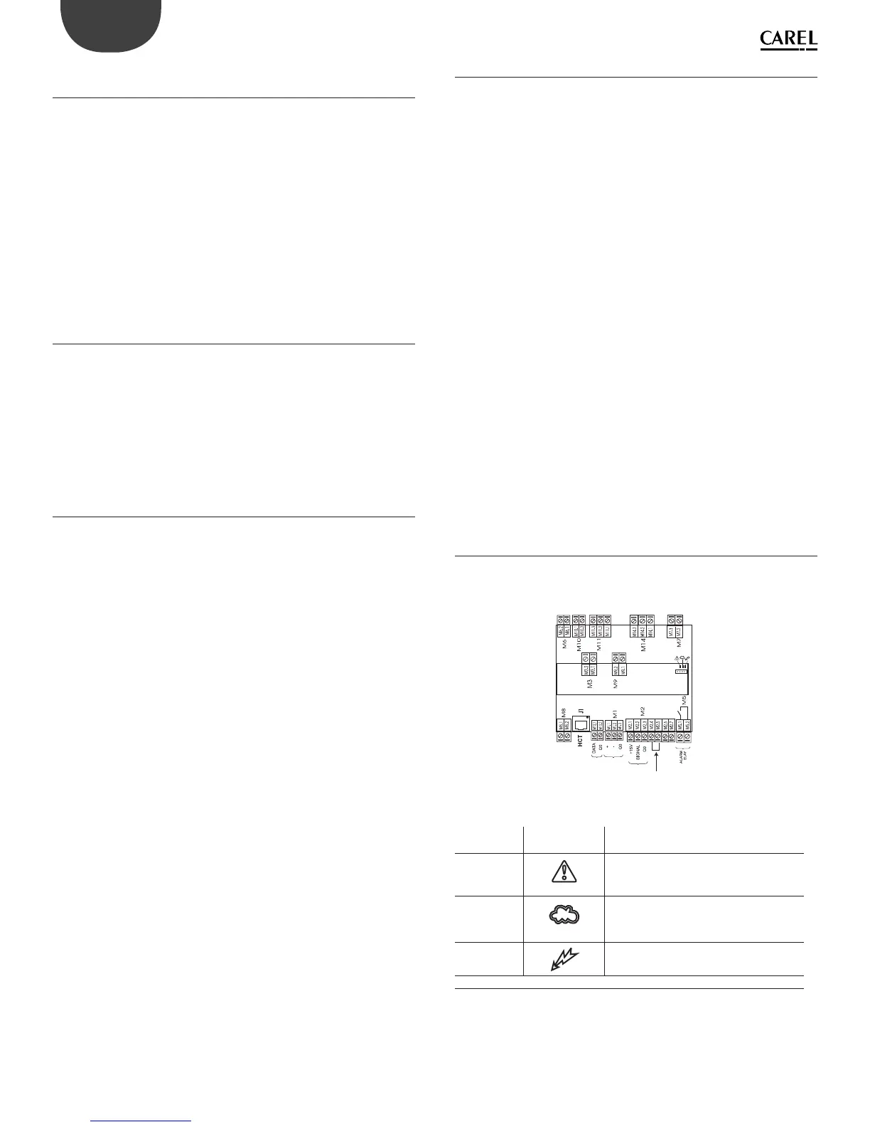
12.9 LEDs on the control board
There are three LEDs fi tted on the expansion board, located above the
control board:
M12
remote
ON-OFF
EXTERNAL
CONTROL
RS 485
TLAN
Fig. 12.b
Key:
LED on
board
Symbol on
display
Meaning
Red
alarm in progress (the type of alarm can be
identifi ed based on the type of fl ashing,
see chap. 8)
Yellow
steam production in progress
(led always on for 100% production, 2
blinkng 20%, 3 blinking 30%, ...)
Green
humidifi er on
Tab. 12.a
NOTE: The yellow and red LEDs are active only if the display is
disconnected.