17
ENG
“UE BASIC” +03U0042EN - rel. 1.3 - 10 May 2013
installatoreutenteassistenza
5. REMOTE TERMINAL AND SUPERVISORY NETWORK
5.1 Remote display terminal
The display terminal can be detached from the humidifi er and moved up
to 30 m (98 feet) away.
21 21 321
M6
32
M7
12 12
M8
12
M5
21
M3
21
M9
COM
R
Y
G
M12
M10
M11
321
M14
M1 M2
123 1234 567
J1
JS6
UEY
controller
2
1
3
2
drain
esc
Fig. 5.a
Key:
1
telephone cable 6 wires (up to
10 m (33 ft)
(1
distance);
2 two EMC fi lters (code 0907858AXX) to be applied to the ends of the
telephone cable;
3 remote display terminal.
Note: to fi ll the empty space left by the display terminal on the
humidifi er, use CAREL kit code HCTREW0000.
(1)
For lengths greater than 10 m (33 ft) use shielded cable with the shield
connected to PE both on the terminal side and the controller side
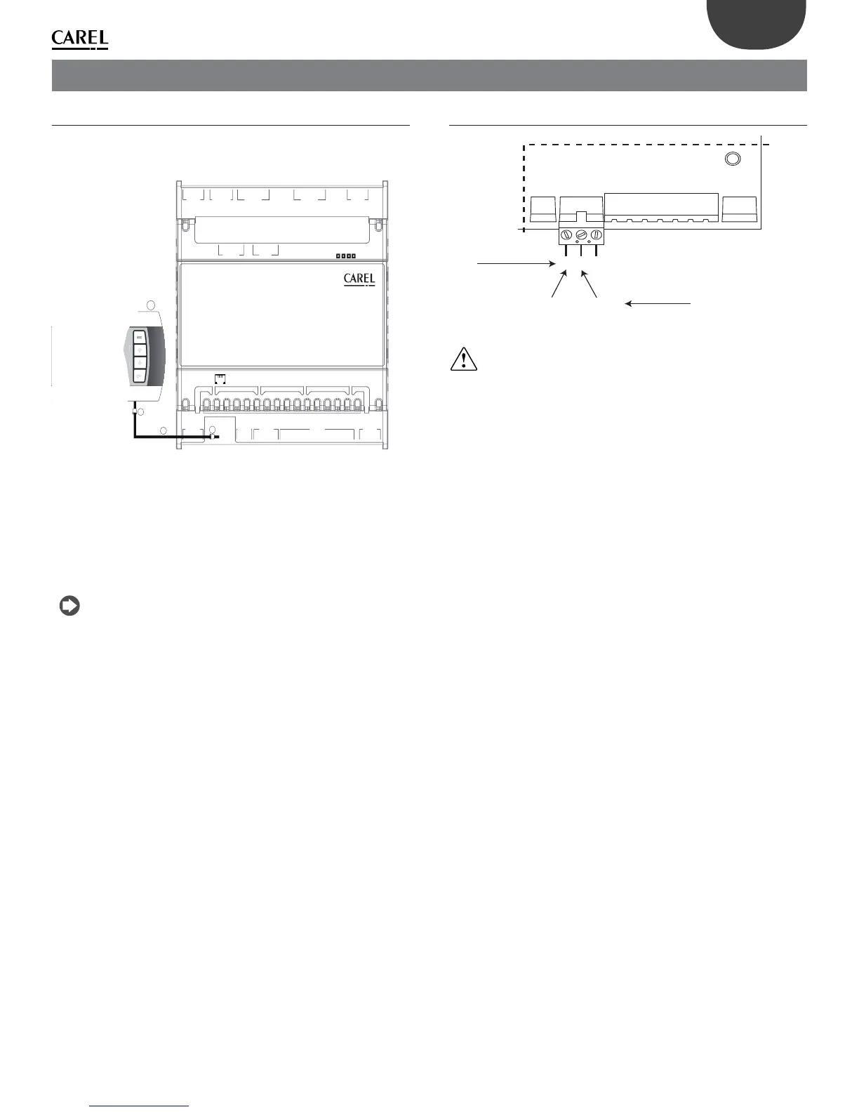
5.2 RS485 supervisory network (M1.1-M1.3)
M.1.1
M.1.2
M.1.3
+-G0
per modelli
UEY*000/UEY*100
Rx- / Tx - Rx+ / Tx +
per modelli UEY*200
Fig. 5.b
Important: for the RS485 connections in household (IEC EN 55014-1)
and residential (IEC EN 61000-6-3) environments, use shielded cable
(with shield connected to PE both on the terminal side and the controller
side) with maximum shielded cable length: specifi ed by the EIA RS485
protocol, equivalent to European stan-dard CCITT V11, using shielded
twisted pair cable, AWG26, 485 input stage impedance 1/8 unit-load (with
this confi guration, a maximum of 256 devices can be connected) laid in
separate conduits from the power cables