28
ENG
“UE BASIC” +03U0042EN - rel. 1.3 - 10 May 2013
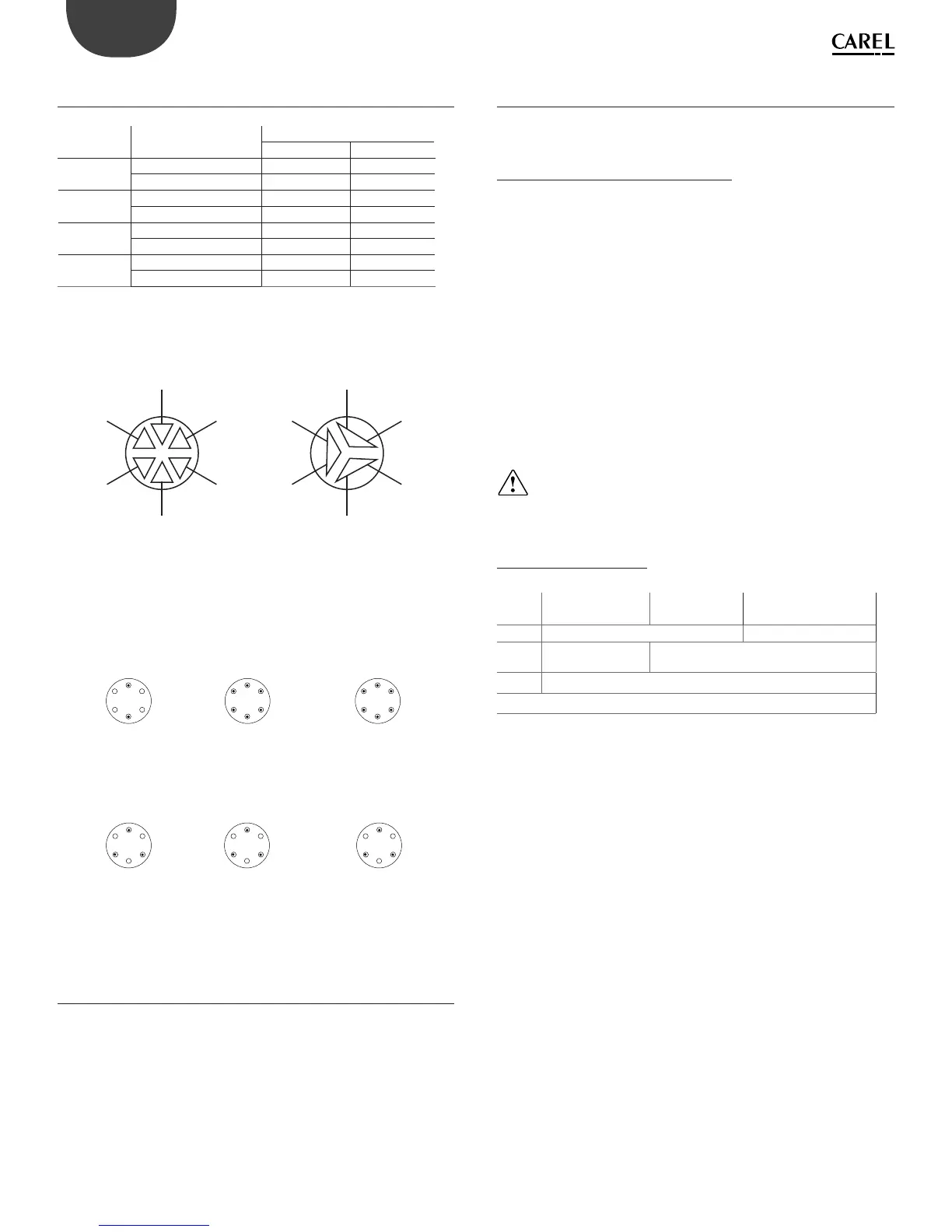
9.5 Cylinder connection, three-phase models
UE025 to UE065
production
(kg/h)
conductivity (μS/cm) power supply (V)
208-230 460-575
25 75/350 µS/cm A B
350/1250 µS/cm B B
35 75/350 µS/cm A B
350/1250 µS/cm A B
45 75/350 µS/cm A B
350/1250 µS/cm A B
65 75/350 µS/cm / B
350/1250 µS/cm / B
Tab. 9.f
The cable ends must be tightened with the top nut to 3 Newton • m
( 27 lbf-in). (units with BL*T5* cylinder only)
1
2
3
1
2
3
A
B
C
F
E
D
A
2
3
3
1
1
2
B
A
B
C
F
E
D
Fig. 9.f
UE001-3-9
single-phase
75...1250 μS
1 = A
2 = D
75...1250 μS
1 = A
2 = C
3 = E
UE003 200 - 230 - 400 - 460 V
three-phase
A
C E
A
D
75...1250 μS
1 = A
2 = C
3 = E
UE005-8 400 - 460 - 575 V
three-phase
C E
A
75...1250 μS
1 = A
2 = C
3 = E
UE0010-18 400 - 460 - 575 V
three-phase
C E
A
UE005 200...230 V
single-phase
175...350 μS
1 = A - E - C
2 = B - F - D
350...1250 μS
1 = A - B - C
2 = D - E - F
A
F
E
B
C
D
UE005-8 / UE010-15
200...230 V three-phase
75...350 μS
1 = A - D
2 = B - E
3 = C - F
350...1250 μS
1 = A - B
2 = C - D
3 = E - F
A
F
E
B
C
D
9.6 Cleaning and maintenance of the other
components
• when cleaning plastic components do not use detergents or solvents;
• scale can be removed using a solution of 20% acetic acid and then rinsing
with water.
Maintenance checks on other components:
□ fi ll solenoid valve. After having disconnected the cables and the tubing,
remove the solenoid valve and make sure the inlet fi lter is clean; if
necessary, clean with water and a soft brush;
□ manifold with drain pump. Check that there are no solid residues in
the cylinder attachment, remove any impurities. Check that the gasket
(o-ring) is not damaged or cracked, replace if necessary. Check that there
are no solid residues in the drain hose;
□ drain pump. Disconnect the power supply, remove the pump and clean
any impurities. Clean the tank from any deposits and check that the
water fl ows freely from the tank to the drain (corresponding to the drain
pump);
□ fi ll tank. Check that there are no obstructions or solid particles and that
the conductivity measuring electrodes are clean, remove any impurities
and rinse;
□ internal tubing kit. Check that the pipes and hoses are free and clear of
impurities, remove any impurities and rinse.
Important: after having replaced or checked the water circuit, make
sure that the connections are tight. Restart the unit and run a number
of fi ll and drain cycles (from 2 to 4), after which, applying the safety procedure,
check for any water leaks.
Fuses in the auxiliary circuits
Fuses UE001 to 018 UE 025 to 065
(460-575V)
UE025-045
( 208-230V)
F1. F2 1 A fast-blow, 10.3x38 2 A fast-blow, 10.3x38
F3
1 A fast-blow, 5x20
ceramic
1 A fast-blow, 10.3x38
F4 4 A T slow-blow 5x20 ceramic
Tab. 9.g
Three-phase and sigle-phase models UE01 to UE018