16
ENG
“UE BASIC” +03U0042EN - rel. 1.3 - 10 May 2013
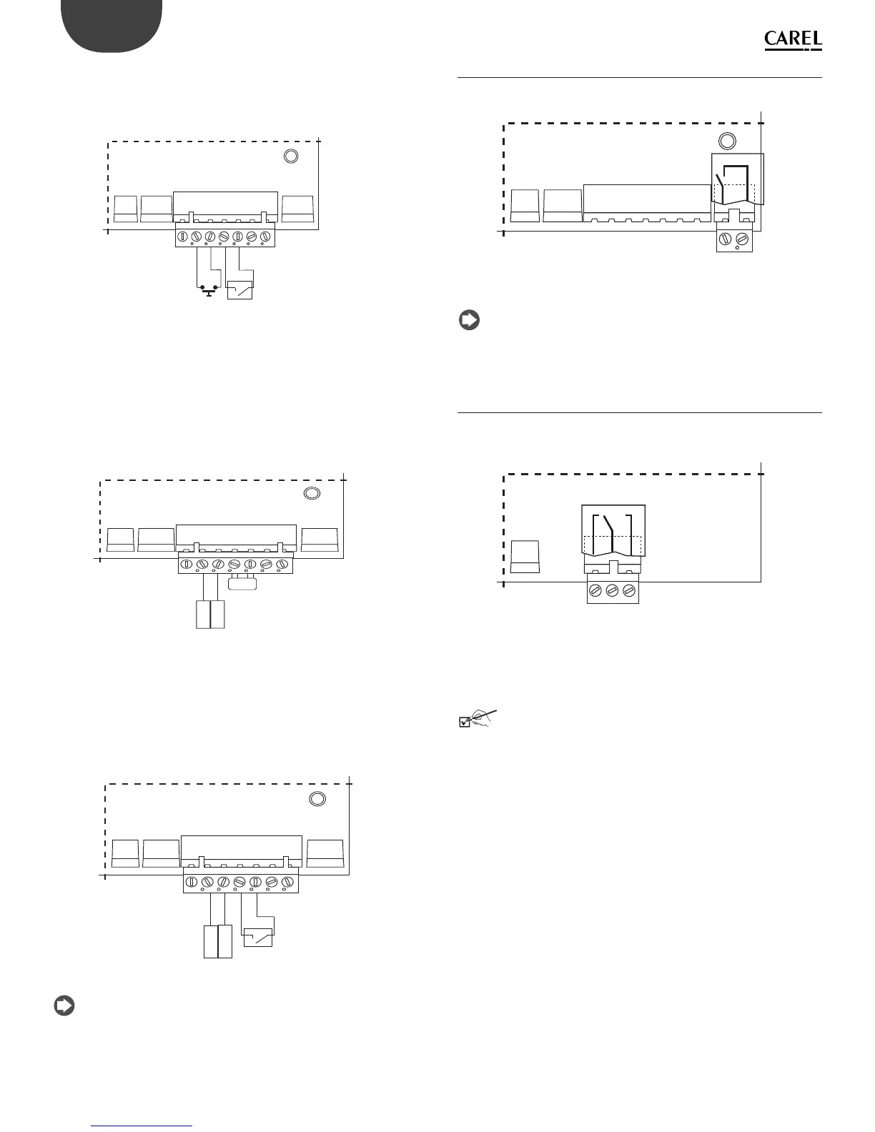
HUMIDISTAT and REMOTE CONTACT (ON/OFF action)
• connect inputs M2.2 and M2.3 (production request) to a humidistat;
• connect inputs M2.4 and M2.5 (enable) to a remote contact (e.g.: switch,
timer,…)
• set parameter A0=0 to enable the ON/OFF action.
M.2.1
M.2.2 M.2.3 M2.4 M.2.5 M.2.6 M.2.7
Fig. 4.e
2. Enable and control steam production using:
PROPORTIONAL EXTERNAL CONTROLLER (modulating action)
• jumper inputs M2.4 and M2.5 (enable)
• connect outputs M2.2 and M2.3 (production request) to an external
controller
• iset parameter A0=1 to enable the modulating action (see chap. 7)
and parameter A2 depending on the signal chosen (0 to 10 V, 2 to 10V,
0..20mA, 4 to 20 mA) (see chap. 7).
M.2.1
M.2.2 M.2.3 M2.4 M.2.5 M.2.6 M.2.7
OUT
REF
Fig. 4.f
PROPORTIONAL EXTERNAL CONTROLLER and REMOTE CONTACT
(modulating action)
• connect inputs M2.4 and M2.5 to a remote contact (enable)
• connect outputs M2.2 and M2.3 (request) to an external controller
• set parameter A0=1 to enable the modulating action (see chap. 7) and
parameter A2 depending on the signal chosen (0 to 10 V, 2 to 10V, 0…20V,
4 to 20 mA) (see chap. 7).
M.2.1
M.2.2 M.2.3 M2.4 M.2.5 M.2.6 M.2.7
OUT
REF
Fig. 4.g
Note: in industrial environments (IEC EN61000-6-2) the signal cables
running from the unit must not exceed 10 m (33 ft)
(1)
in length: steam
production signal cable (terminals M2.1...M2.3), remote on/off input
(terminals M2.4...M2.5) and cable shields for RS485 communication.
4.4 Alarm contact (M5.1 - M5.2)
Contact available for the remote signalling of one or more alarms.
M.5.1M.5.2
Fig. 4.h
Electrical specifi cations: 250 Vac; Imax: 2 A resistive 2 A inductive.
Note: use clamps on the relay terminal blocks (alarm, utilities) to
prevent the cables from being detached.
4.5 Auxiliary contact: production request
present, external fan control) (M14.1 - M14.3)
Relay contact that indicates the presence of the steam production request. It
can also be used to control an external fan (see chap. 12.7)
M.14.1 M.14.2
M.14.3
Electrical specifi cations: 250 Vac; Imax: 8 A resistive 2 A inductive.
Final checks
The following conditions represent correct electrical connection:
□ the rated voltage of the appliance corresponds to the rated supply
voltage;
□ the fuses installed are suitable for the line and the power supply
voltage;
□ a mains disconnect switch has been installed to disconnect power to the
humidifi er when required;
□ the humidifi er has been correctly earthed;
□ the power cable is fastened using the tear-proof cable gland;
□ terminals M2.4 and M2.5 are jumpered or connected to an enable-
operation contact;
□ if the humidifi er is controlled by an external control device, the earth of
the signal is electrically connected to the controller earth.