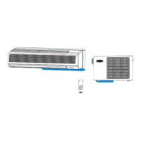
Outdoor Unit
Installation
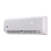
Step 4: Connect signal and power cables
The outside unit’s terminal block is protected
by an electrical wiring cover on the side of
the unit. A comprehensive wiring diagram is
printed on the inside of the wiring cover.
WARNING
BEFORE PERFORMING ANY
ELECTRICAL OR WIRING WORK,
TURN OFF THE MAIN POWER TO
THE SYSTEM.
1. Prepare the cable for connection:
USE THE RIGHT CABLE
● Indoor Power Cable (if applicable):
H05VV-F or H05V2V2-F
● Outdoor Power Cable: H07RN-F
● Signal Cable: H07RN-F
CHOOSE THE RIGHT CABLE SIZE
The size of the power supply cable,
signal cable, fuse, and switch needed is
determined by the maximum current of the
unit. The maximum current is indicated on
the nameplate located on the side panel of
the unit. Refer to this nameplate to choose
the right cable, fuse, or switch.
a. Using wire strippers, strip the rubber
jacket from both ends of cable to reveal
about 40mm (1.57in) of the wires inside.
b. Strip the insulation from the ends of the
wires.
c. Using a wire crimper, crimp u-lugs on the
ends of the wires.
PAY ATTENTION TO LIVE WIRE
While crimping wires, make sure you
clearly distinguish the Live (“L”) Wire from
other wires.
WARNING
ALL WIRING WORK MUST BE
PERFORMED STRICTLY IN
ACCORDANCE WITH THE WIRING
DIAGRAM LOCATED INSIDE OF WIRE
COVER OF THE OUTDOOR UNIT.
2. Unscrew the electrical wiring cover and
remove it.
3. Unscrew the cable clamp below the
terminal block and place it to the side.
4. Connect the wire according to the wiring
diagram, and rmly screw the u-lug of
each wire to its corresponding terminal.
5. After checking to make sure every
connection is secure, loop the wires
around to prevent rain water from owing
into the terminal.
6. Using the cable clamp, fasten the cable
to the unit. Screw the cable clamp down
tightly.
7. Insulate unused wires with PVC electrical
tape. Arrange them so that they do not
touch any electrical or metal parts.
8. Replace the wire cover on the side of the
unit, and screw it in place.
Cover
Screw
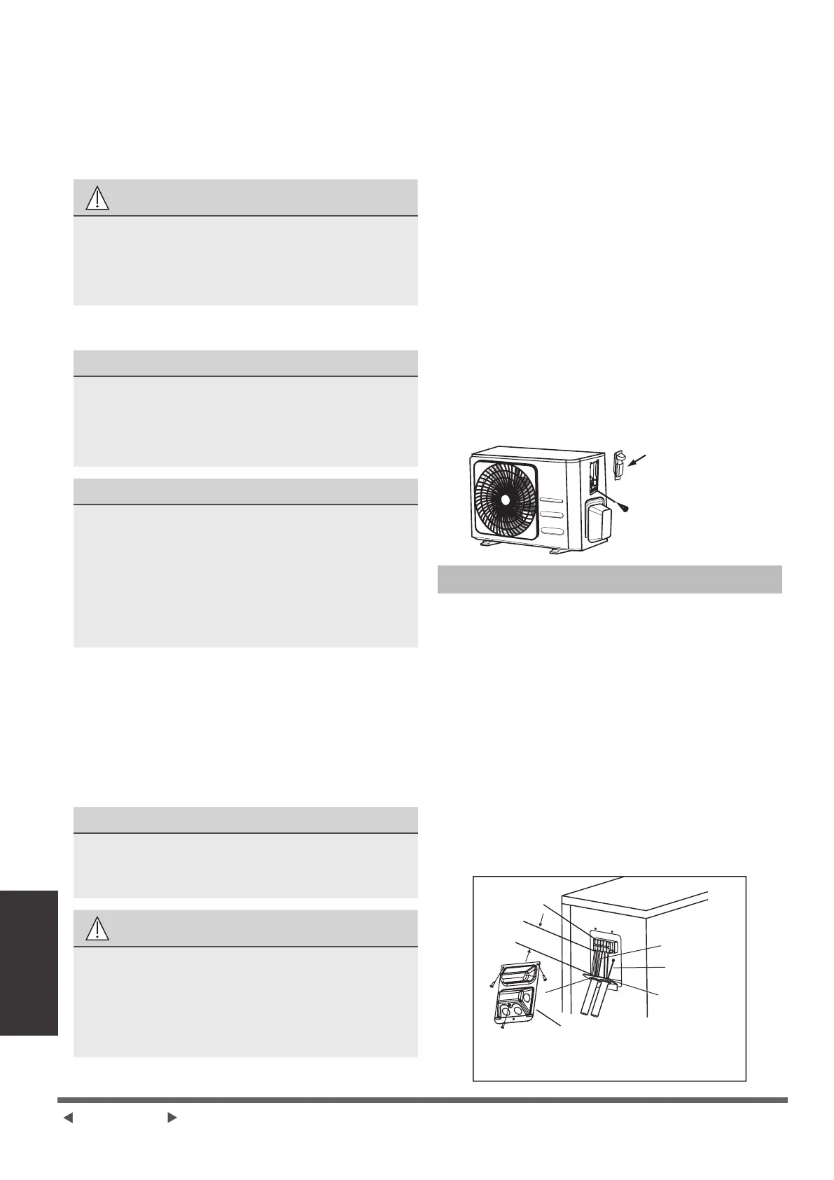
In North America
1. Remove the wire cover from the unit by
loosening the 3 screws.
2. Dismount caps on the conduit panel.
3. Temperarily mount the conduit tubes (not
included) on the conduit panel.
4. Properly connect both the power supply
and low voltage lines to the corresponding
terminals on the terminal block.
5. Ground the unit in accordance with local
codes.
6. Be sure to size each wire allowing
several inches longer than the required
length for wiring.
7. Use lock nuts to secure the conduit tubes.
G
Terminal block
Connecting cable
Power supply cord
Conduit panel
Wire Cover
Please select the appropriate through-hole
according to the diameter of the wire.
Over 1.57in. (40mm)
Page 14-GB
 Loading...