Indoor Unit
Installation
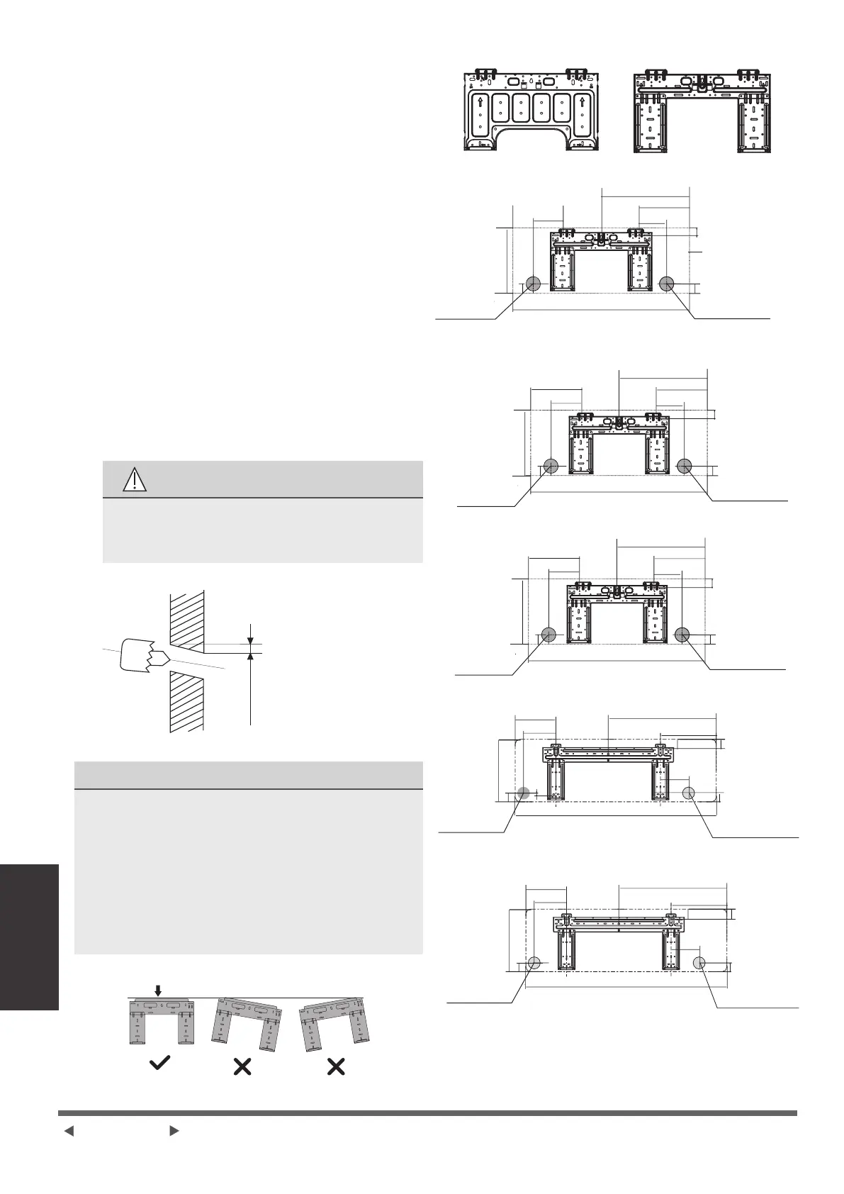
Step 3: Drill wall hole for connective
piping
1. Determine the location of the wall hole
based on the position of the mounting
plate. Refer to Mounting Plate
Dimensions.
2. Using a 65mm (2.5in) or 90mm (3.54in)
(depending on models )core drill, drill a
hole in the wall. Make sure that the hole
is drilled at a slight downward angle,
so that the outdoor end of the hole is
lower than the indoor end by about 5mm
to 7mm (0.2-0.275in). This will ensure
proper water drainage.
3. Place the protective wall cuff in the
hole. This protects the edges of the hole
and will help seal it when you nish the
installation process.
CAUTION
When drilling the wall hole, make sure
to avoid wires, plumbing, and other
sensitive components.
Wall
Indoor Outdoor
5-7mm
(0.2-0.275in)
MOUNTING PLATE DIMENSIONS
Different models have different mounting
plates.
For the different customization
requirements, the shape of the mounting
plate may be slightly different. But the
installation dimensions are the same for the
same size of indoor unit.
See Type A and Type B for example:
Correct orientation of Mounting Plate
Type A Type B
348.4mm (13.7in)
403mm (15.9in)
418mm (16.5in)
527mm (20.7in)
603mm (23.7in)
247mm (9.7in)
322mm (12.7in)
139mm
(5.5in)
173mm
(6.8in)
165mm (6.5in)
199mm (7.8in)
106mm (4.2in)
129mm (5.1in)
973mm (38.3in)
1082mm (42.6in)
318mm (12.5in)
338mm (13.3in)
48mm (1.9in)
29mm (1.1in)
54mm (2.1in)
835mm (32.9in)
246mm (9.7in)
121mm (4.8in)
244mm (9.6in)
190mm (7.5in)
297mm (11.7in)
47mm (1.8in)
231mm (9.1in)
121mm (4.8in)
Left rear wall hole
65mm (2.5in)
Left rear
wall hole
65mm (2.5in)
Left rear
wall hole
65mm (2.5in)
Left rear wall hole
65mm (2.5in)
Left rear wall hole
90mm (3.54in)
Indoor unit outline
Right rear wall hole
65mm (2.5in)
Right rear wall
hole 65mm (2.5in)
Right rear wall hole
65mm (2.5in)
Right rear wall hole
65mm (2.5in)
Right rear wall hole
90mm (3.54in)
Model A
Model B
Model C
Model D
Model E
101mm (4.0in)
230mm (9.1in)
190mm (7.5in)
805mm (31.7in)
722mm (28.5in)
290mm (11.4in)
49mm (1.95in)
297mm (11.7in)
47mm (1.8in)
37mm
(1.45in)
49mm
(1.95in)
36mm
(1.4in)
53mm
(2.1in)
53mm
(2.1in)
37mm
(2.1in)
55mm
(2.1in)
48mm
(1.9in)
54mm
(2.1in)
36mm
(1.4in)
179mm (7.1in)
136mm (5.4in)
NOTE: When the gas side connective pipe
is ø16mm (5/8in) or more, the wall hole
should be 90mm (3.54in).
Page 06-GB
 Loading...