5.2.13 Replacing the MK6 Replacement EEPROM (1-44782-K182) only
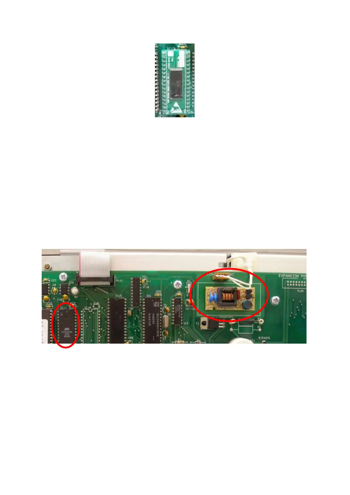
Figure 153 1-44782-K182 Board
1. Switch off the power to the system.
2. Carefully remove the EEPROM from the socket, IC17 on the Main Control Processor Board.
3. Plug the new EEPROM into the socket, ensure it is the right way up (as shown on the image on the
left) and that all the pins are correctly aligned in the socket.
4. Switch on the power to the system.
5. Re-program the panel configuration and alarm levels.
5.2.14 Replacing the EEPROM where the EEPROM is soldered directly to the Main Control Processor
Board.
Please also note that the LCD Backlight inverter circuitry (labelled as 'Inverter 1') in the image below is
not supported on Revision 6 and above of the Main Control Processor Board.
The original Control Panel display used a CCFL backlight that contained small amounts of mercury now
prohibited by the RoHS directive.
To comply with this directive Carrier have re-engineered the LCD and the display driver electronics on
the Main Control Processor Board.
Revision 6 and above of the Main Control Processor Board are now unable to drive the older CCFL backlit
display. The display will remain black and so to remove the Replace EEPROM message the vessel will
need to install a new Main Control Processor Board and a new LCD module.
Order part number 1-43782-K178 for the Main Control Processor Board and LCD Assembly.
5.2.15 Removal & Replacement of the Main Control Processor Board and LCD Display module
1. Switch off the power to the system.

 Loading...