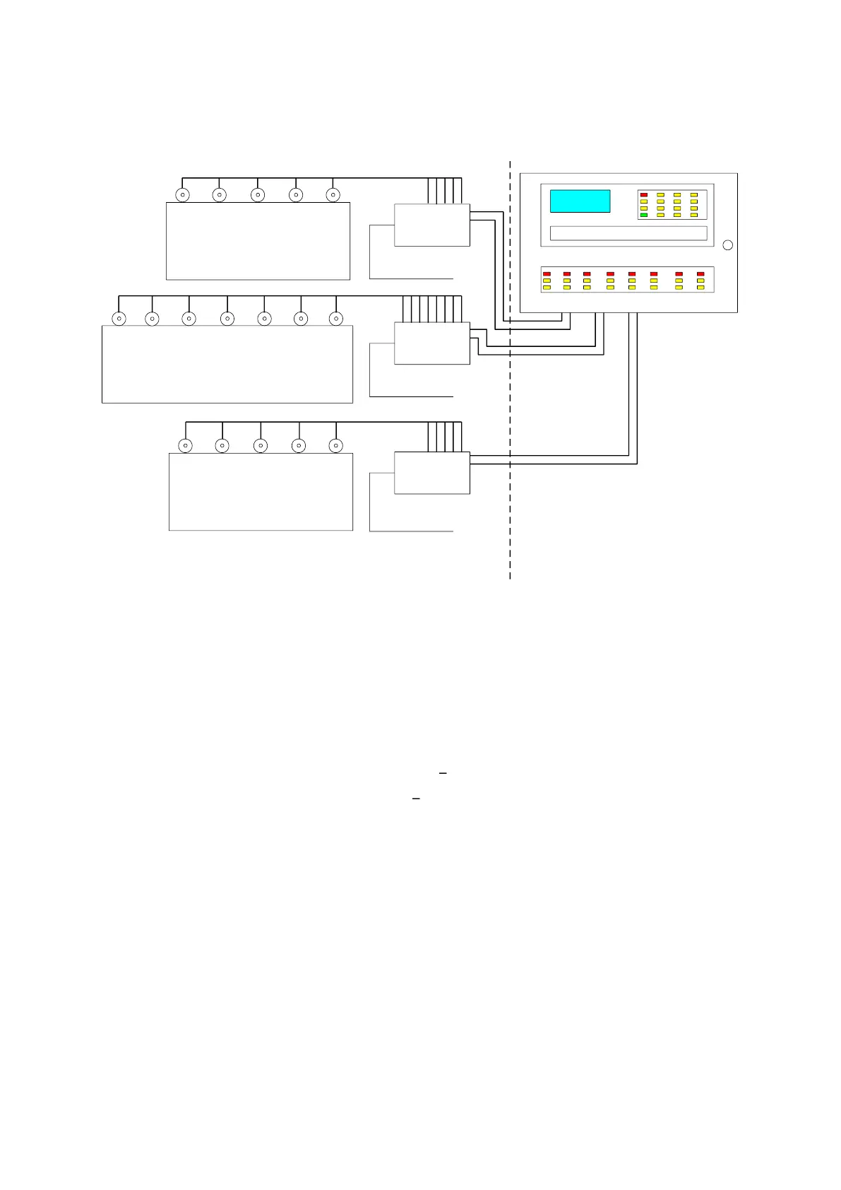
Each detector communicates electronically over a serial data link via the engine mounted Junction Box
with the Control Panel designed to be mounted within the Engine Control Room. This eliminates the need
to enter the machinery space in alarm conditions.
Figure 4 Typical System Configuration
1.3 TECHNICAL SPECIFICATION
Detector
Mounting ¾ inch BSP
Enclosure Rating IP65
Address Switch 2 x 10 position (0 to 99)
Material Sample Tube Carbon Loaded PTFE
Detector Black Du Pont Nylon 70G33L
Indicators Green Detector On
Red Alarm
Amber Detector Fault
Power Consumption 2.8W
Operating Temperature Rating 0 to 70
o
C
Storage Temperature Rating -20
o
C to 60
o
C
Height 175mm
Width 90mm
Length 205mm
Weight 0.6kg

 Loading...