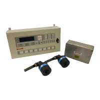
2.2 CONTROL PANEL CABLING
24v DC Input supply
The Mk6 Control Panel should be powered from a floating 24v DC supply (+30% -25%) suitably rated
depending on the number of detectors connected.
PLEASE NOTE: - The Control Panel may not operate correctly if the external 24v power supply
is referenced to the vessel earth and there is also a risk the input protection circuitry in the units
could be damaged.
Cables should be segregated from high voltage cables and follow good installation practice.
Cable type-2 Cores + Earth, CSA 2.5mm
2
(50/0.25mm), flexible stranded bare copper conductors, low
smoke halogen free insulation, cores laid up, braided screen, low smoke halogen free sheath grey,
outside diameter 9.8mm, operating temperature 0ºC + 80ºC.
Suggested cables
Lapp Kabel CY cable 3 core 2.5mm
2
Prysmian LSM-HF 3 core 2.5mm
2
Helkama LKAM-HF 3 core 2.5mm
2
Refer Error! Reference source not found. for connector location.
Refer Figure 36 for wiring drawing.
Communications
Cable type Individually screened 2 pair data cable, 24AWG, low capacitance, low smoke halogen free.
Outer diameter 7mm (max)
Cables should be segregated from high voltage cables and follow good installation practice
Approved cables:
FS Cables 2402PIFFH
Beldon 9729
Helkama RFE-HF(i) 2x2x0.75
Jinro 60V RCOP(IS)
The above cable should be used to connect between the Control Panel and the Junction Boxes.
Refer Error! Reference source not found. for connector location.
Refer Figure 36 for wiring drawing.
Relay Outputs
The relay outputs are rated at 30v DC at 1amps.
2 Cores + Earth, CSA 2.5mm
2
(50/0.25mm), flexible stranded bare copper conductors, low smoke
halogen free insulation, cores laid up, braided screen, low smoke halogen free sheath grey, outside
diameter 9.8mm, operating temperature 0
o
C + 80
o
C.
Cables should be segregated from high voltage cables and follow good installation practice
Approved cables:
Lapp Kabel CY cable 3 core 2.5mm2
Prysmian LSM-HF 3 core 2.5mm2
Helkama LKAM-HF 3 core 2.5mm2
Refer Error! Reference source not found. for connector location.
Refer Figure 36 for wiring drawing.
2.3 JUNCTION BOX MOUNTING
The Junction Box is available with 20mm input glands, (1-D4720-001-14) or 25mm input glands, (1-
53836-K224-14), and is designed for on-engine mounting. It is recommended that the box is installed as
near to the centre of the engine as possible to minimise Detector cable lengths. Mounting is via the four
M6 locating holes in the box. Sufficient space must be left around the Junction Box to allow access to

 Loading...