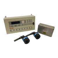
6.2.1 Junction Box PCB Replacement
1. Power down the system.
2. Disconnect all external wires from the Junction Box Board ensuring each wire is identified to allow
correct reconnection to the replacement board.
3. Remove 4 fixing screws and washers. Remove the PCB.
4. Fit the new PCB with the 4 screws and washers,
5. Reconnect the external wires into the correct terminals.
6. Switch on system and allow it to initialise.
7. Ensure no communications faults are indicated on the Control Panel.

 Loading...