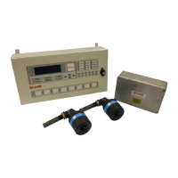
Figure 139 Loss of communications on consecutive detectors
Having established which detectors are in fault it is necessary to establish the cause of the fault using
the following steps.
1. Remove the power from the system
2. Using a multi-meter measure the continuity between the c+ in (yellow), c+ out (brown) and between
c- in (white), c- out (pink) terminals in the Junction Box for the detectors before and after the first
detector with communications fault
3. In each case a short circuit should be measured
If a short circuit is not measured the detector cable should be replaced.
4. After checking the detector cables for continuity measure the continuity between the c+ in (yellow)
terminals and between c- in (white) terminals in the Junction Box for the detectors before and after
the first detector with communications fault.
5. In each case a short circuit should be measured
If a short circuit is not measured the Junction Box PCB should be replaced.
5.2.2.4 All detectors on an engine in fault
Having established which engine is in fault it is necessary to establish the cause of the fault using the
following steps.
1. Check that the detectors are powered, i.e. the green LED on each detector is on.
If the power is present, go to 9.
2. Isolate all detectors on the engine and disconnect detector cables from the detector heads.
3. Remove the power from the system.
4. Check the continuity of the glass fuse in the Junction Box.
If the fuse has blown it should be replaced with a 4A Slow Blow 20mm fuse.
5. Switch on the power to the system.

 Loading...