DISTRIBUTION SYSTEMS - PRIMARY HYDRAULIC POWER SYSTEM
Relief v alve - Pressure test (A.10.A.16 - F.40.A.30)
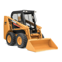
435, 445, 445CT
CAS1808
NOTE: Flat face couplers are not included with the CAS-1808 Flowmeter Fitting Kit or the CAS-1804 Pressure
Test Fitting K it.
1. Park the machine on a level surface. Lower the
loader bucket to the floor.
2. The oil must be at operating temperature. To heat
the oil, do the following steps:
A. With the engine running at fu ll throttle, hold the
bucket control lever in the ROLLBACK position for
10 seconds.
B. Put the bucket control lever in the NEUTRAL
position for 10 seconds.
C. Repeat steps A and B until the temperature of
the oil is 52° C (125° F) or the side of the reservoir
is very warm.
3. Useapressu
re gauge with a capacity of at least
276 bar (4000 psi). Connect the pressure gauge to
one of the auxiliary hydra ulic couplers on the le ft
hand loader
arm.
4. Run the engin e at full throttle. Actuate the auxiliary
hydraulic
flow control pedal to pressurize the
hydraulic line which has the pressure gauge.
Record the indication on the pressure gauge. Then
return th
e auxilia ry hydr aulic flow control pedal to
the Neutral position and decrease the engine speed
to low idle. St op the engine.
5. Compare the indication with the specification
Relief valve - General specification (A.10.A.16 -
D.40.A.10). If the indication is not correct, adjust the
main relief valve. Then do the pressure check again
to make sure that the s etting is correct.
1 04/05/2005
A.10.A / 29