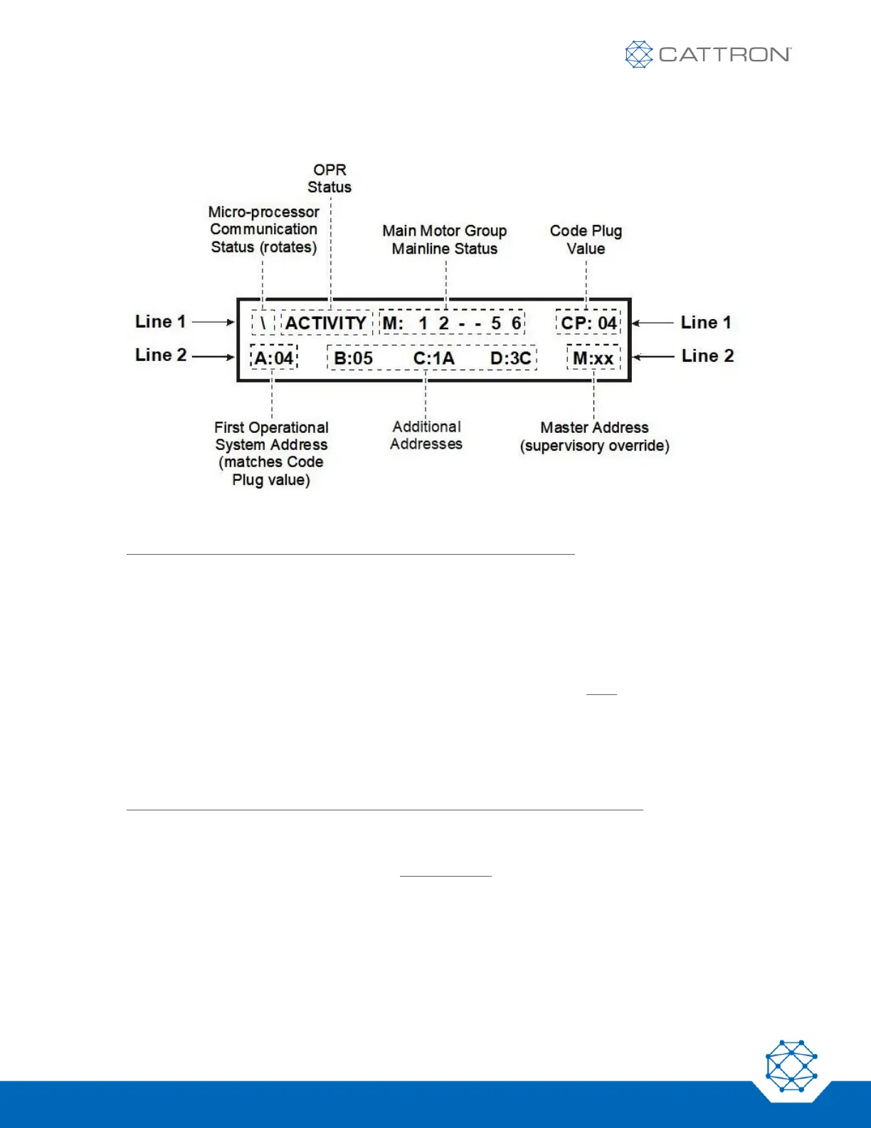
Referring to Figure 12, the normal operating display is divided into several areas of information as follows:
Figure 12: Normal Operating Display (Default Screen)
Line 1: Referring to Figure 12, display Line 1 contains four areas of information:
The Micro-processor Communication Status area displays a rotating bar. The rotation of the bar indicates that
the decoder’s microcomputers are passing information among themselves and cross checking data.
The OPR Status area provides the status of the Operate (OPR) relays. As shown in Figure 12, the word
‘ACTIVITY’ is displayed whenever the controller is ON and transmitting. The ‘ACTIVITY’ indicates that both OPRs
are ON. A display showing ‘OPR1 – ’ or ‘ – OPR2’ indicates that only the displayed individual OPR is turned ON.
This is typical during initial testing of the OPRs when the controller is turned on.
The Main Motor Group Mainline Status area provides the operational status of each of the motor group’s
mainline contactors (up to six). Using the example shown in Figure 12, motor groups 1, 2, 5 and 6 are operating.
The absence of the numbers 3 and 4 indicates those two groups are OFF.
The Code Plug Value area simply displays the code plug value of the decoder. A code plug must always be
installed before the address will work. Note that the code plug will always determine the system operating
address(es).
Line 2: Referring to Figure 12, display Line 2 shows the valid system operating addresses:
The First Operational System Address ‘A’ shows the engineered value of the code plug. If this hexadecimal
number does not match the code plug value in line 1, the system will not function.
Sequential Additional Addresses ‘B’, ‘C’, and ‘D’, if programmed, will be displayed next.
The Master Address provides the address of a supervisory/override-capable controller. ‘xx’ is displayed when no
supervisory override controller is required.