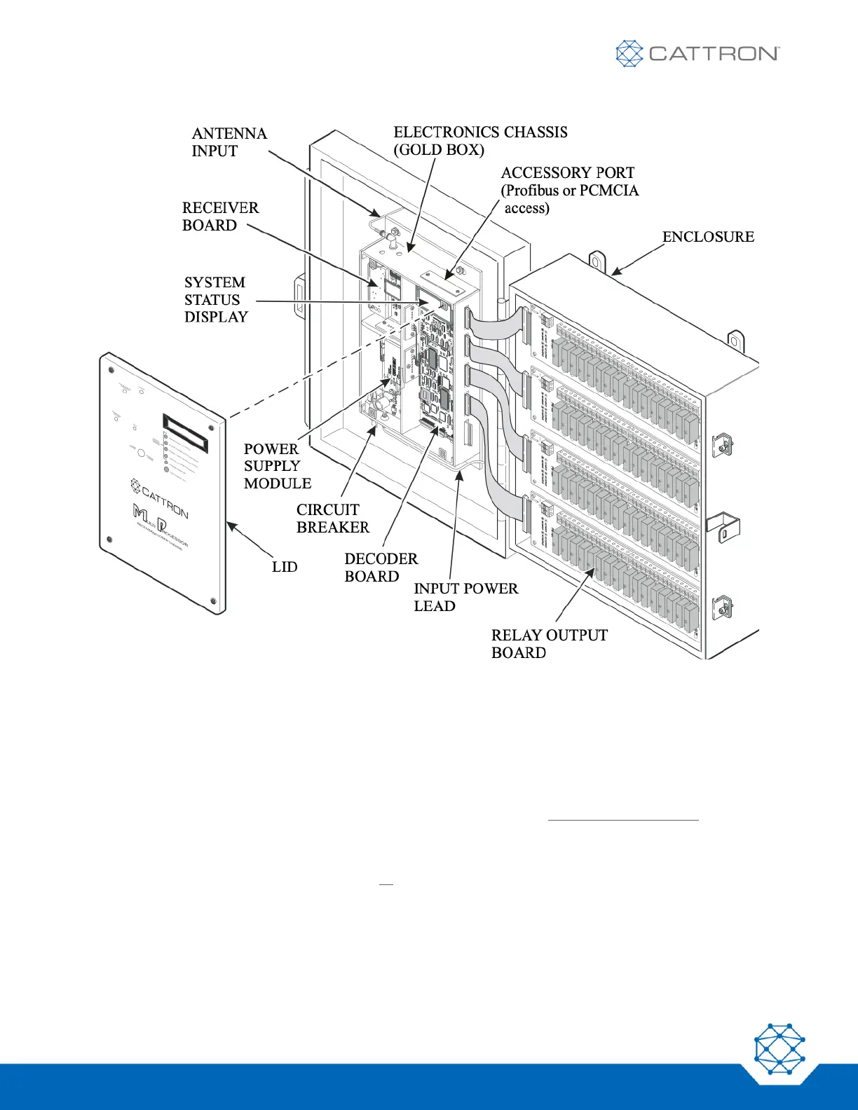
Figure 1: MP Series Receiver/Decoder Component Layout (Crane Variant)
4.3 Functional Description
Referring to Figure 1 above, the receiving and decoding hardware, along with the relay interface board, is housed
within a NEMA 12 (IP65) or other optional enclosure. The decoder has a system status display to show system
status and act as central reference point. The output interface is handled by solid state plug-in relays rated for
heavy-duty resistive and inductive industrial loads. Each output function relay has two screw terminals, an output
fuse and an LED indicator. The output contact of each critical and directional output relay is also monitored by the
decoder, which is used to sense and verify each of these relay outputs. Upon detection of a fault condition, the
Motor Main Relays or Operate (OPR) relays and all relay outputs are disabled. This is the Automatic Safety
Override (ASO) function, a safety feature found on all Cattron Portable Remote Control systems.