The C16QS module can be powered by a single power supply mode.
✓ The module has 4 channels of power supply, two VBAT_BB and two VBAT_RF pins.
✓ The module power supply range is between 3.4V – 4.2V
✓ It is recommended to use 3.7 V/830 mA power supply.
✓ If the module's operating voltage drop causes the VCC supply voltage to be too low or the supply
current is insufficient, the module may shut down or restart. Therefore, to reduce the power fluctuation
of the module when working, it is necessary to use a low-ESR value of the voltage regulator capacitor,
the power pin and the ground pin should be connected and can provide sufficient power supply
capability.
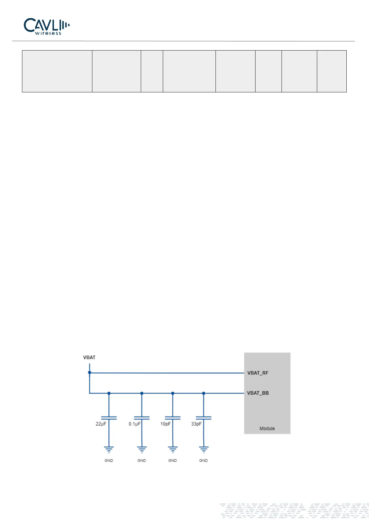
✓ The external power supply is connected to the module from a single voltage source and can be expanded
to two sub paths with star structure.
✓ The VBAT_BB line width should be within 1mm, and the VBAT_RF line width should not be less than
2mm.
✓ The GNSS_VDD voltage is for powering ON GNSS IC and GNSS_EN is to start the NMEA streaming in
the independent operation mode of GNSS and LTE. In normal working mode, both pins can be left
floating.
✓ For more information, refer C16QS GNSS Application Note.
To ensure that the power supply is sufficient, a 10pF, 33pF, 0.1µF, 22µF ceramic capacitors can be added to
improve the performance and stability of the system.
Figure 3 VBAT power supply