• An external LDO can be selected to supply power according to the active antenna requirement.
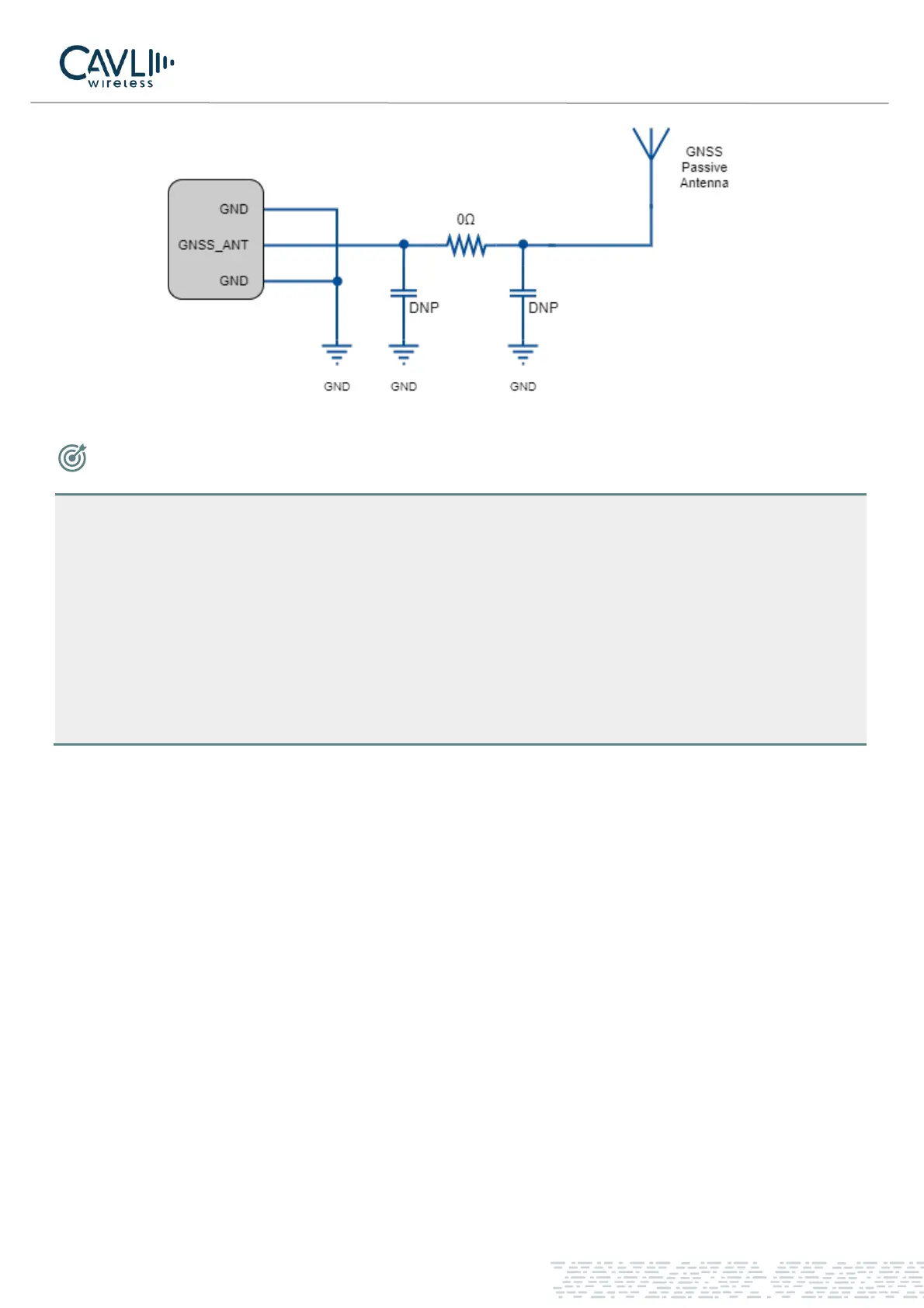
• If the module is designed with a passive antenna, then the VDD circuit is not needed.
• The LTE_MAIN antenna is distributed reasonably to improve the receiving sensitivity.
• In actual use, the antenna board can be debugged and optimized according to the user's circuit board.
• Antenna impedance traces need to be away from digital signal lines, power supplies and other
interference signals.
• The antenna impedance traces need to be three-dimensionally packaged, and the ground holes are
added on both sides of the trace to isolate.
3.14.1 RF Trace Reference
The main set of the C16QS module are extracted by pad. The antenna pad to the antenna feed point must use
microstrip lines or other types of RF traces. The characteristic impedance of the signal line should be
controlled at 50Ω.
The impedance of the RF signal line is determined by the material's dielectric constant, trace width (W), ground
clearance (S), and reference ground plane height (H). Therefore, the RF trace requires an impedance
simulation tool to calculate the impedance of the RF trace.