Table 3-22 ADC Pin Definitions
3.14 Antenna
The C16QS module provides two antenna interfaces, one main set antenna interface, which is responsible for
the CAT .1bis signals of the transceiver module, and another GNSS antenna interface.
The GNSS antenna interface is L1.
The impedance of the antenna interfaces are 50 ohms.
Table 3-23 Antenna interface pin definition
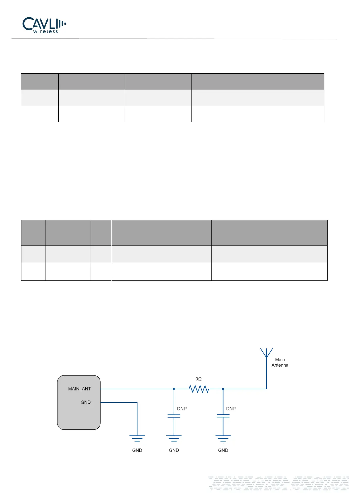
The pin-3 of the C16QS is the main set antenna interface.
To facilitate the debugging of the antenna, a π-type matching circuit needs to be added to the main board, and
a 50-ohm impedance line is taken.
Recommended circuit is shown below:
Figure 15 Main antenna matching circuit