EasyManua.ls Logo

Cavli Wireless C16QS - Module IO Level

Default Icon
74 pages
Print Icon
To Next Page IconTo Next Page
To Previous Page IconTo Previous Page
Loading...
51
www.cavliwireless.com
C16QS Hardware Manual
✓ The PCB layout of the protective device should be as close as possible to the "V" line to avoid the "T"
line
✓ The ground plane around the module guarantees integrity and should not be split
✓ ESD control of the surrounding environment and operators is required during module production,
assembly and laboratory testing
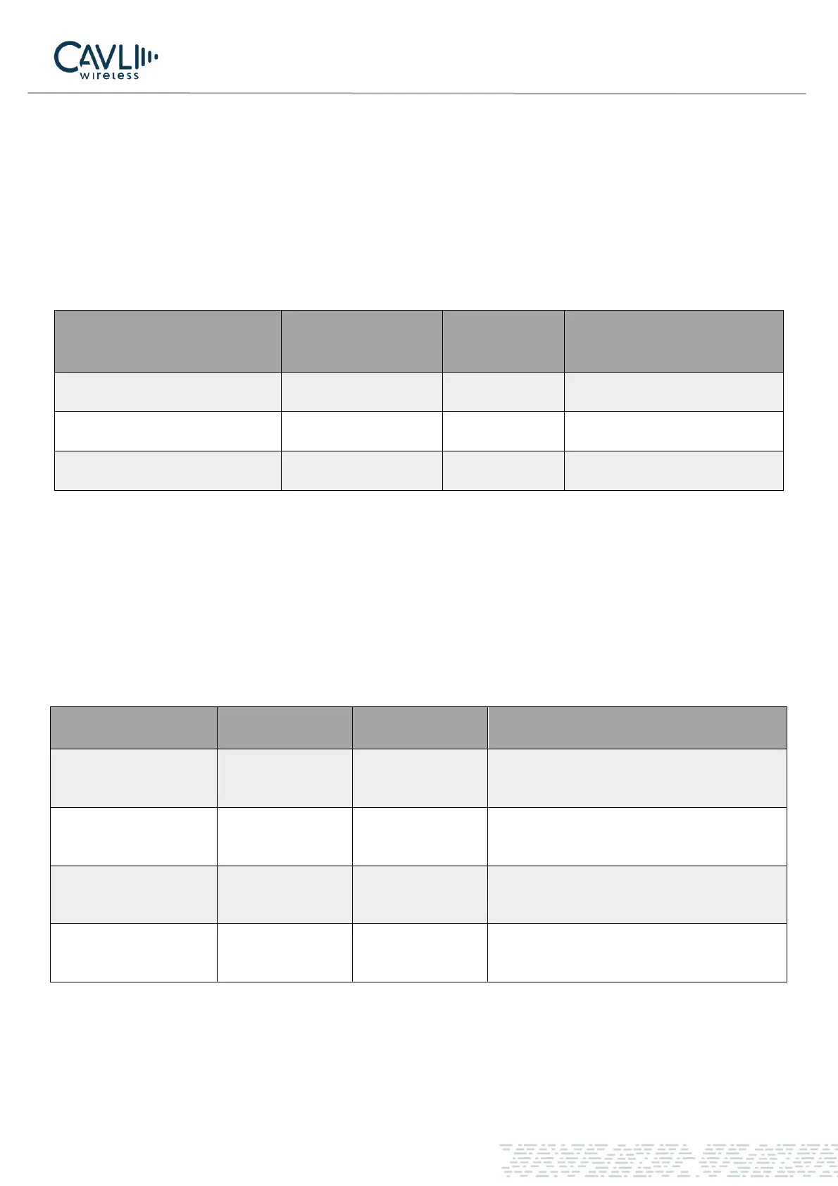
Table 5-2 C16QS ESD Features
5.4 Module IO Level
The C16QS module IO levels are as follows:
Table 5-4 Electrical Characteristics of C16QS module
Test port
Contact discharge
Air
discharge
Unit
USB interface
±4
±8
KV
USIM interface
±4
±8
KV
VBAT power supply
±4
±8
KV
Parameter
Description
Minimum
Maximum
VIH
High level input
voltage
0.65* VDD_EXT
VDD_EXT+0.3V
VIL
Low level input
voltage
-
0.35*VDD_EXT
VOH
High level output
voltage
VDD_EXT-0.45V
VDD_EXT
VOL
Low level output
voltage
0
0.45V

Table of Contents