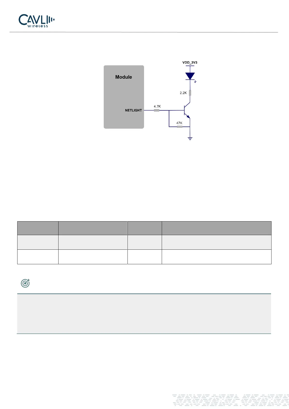
The LED network indicator reference design is as follows:
Figure 12 Net light circuit diagram
When the module enters flight mode, the RF function do not work and all AT commands related to RF functions
will be inaccessible. This mode can be set by
✓ Software: AT+CFUN=4
Table 3-16 Network Indicator Pin Definition 2
NOTE
• The brightness of the network indicator can be adjusted by adjusting the current limiting resistor,
which can be adjusted to a maximum of 40 mA.
• Remember to use only one among the pins 21 and 75. While using one, keep the other floating.