Assembly and operating instructions
CENTAX-G
020G-00050…00090-F.10
CENTA Antriebe Kirschey GmbH 17 / 52
Measure the radial misalignment with a dial gauge (see Fig. 5-2).
Attach the dial gauge to the flange/hub/adapter (E/3/17).
Set the sensor of the dial gauge radially against the centring.
Turn the flange/hub/adapter (E/3/17) with dial gauge and flywheel (C)
slowly by 360°.
Align the units (calculated deviation ≤∆K
R max
).
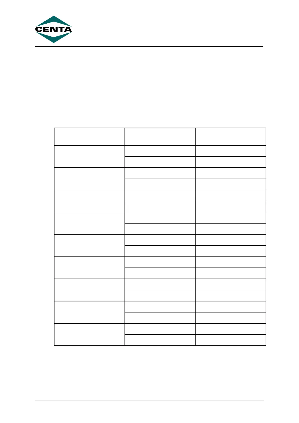
The permissible radial alignment tolerance ∆K
R max
can be found in the following
table.
Table 5-1 Permissible radial alignment tolerance