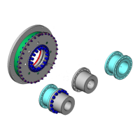
Assembly and operating instructions
CENTAX-G
020G-00050…00090-F.10
CENTA Antriebe Kirschey GmbH 45 / 52
9.2 Disconnecting the rubber element (1.1) and the membrane
See Fig. 6-15 and 6-14:
Loosen the screws (1.2.4) of the connection membrane (1.2.1) and
rubber element (1.1) and remove with the washers (1.2.6), the nuts (1.2.5)
and the rings (1.2.2).
Loosen the screws (1.2.8) of the connection membrane (1.2.1) and
rubber element (1.1) and remove with the washers (1.2.7), the nuts (1.2.9)
and the bushes (1.2.3).
9.3 Dismantling the membrane (1.2.1)
Dismantle the membrane (1.2.1) as appropriate for the supplied coupling
size (see installation drawing):
Dismantling the membrane (coupling sizes 00050 – 00075),
see chapter 9.3.1.
Dismantling the membrane (coupling sizes 00078 – 00090),
see chapter 9.3.2.
9.3.1 Dismantling the membrane of the coupling sizes 00050…00075
See Fig. 6-12:
Loosen and remove the screws (1.10) of the connection ring (1.9),
membrane (1.2.1) and ring (1.4).
Pull the ring (1.9) off the centring of the flange/hub/adapter (E/3/17) and
place it on the flange/hub/adapter (E/3/17).
Pull the membrane (1.2.1) off the centring of the flange/hub/adapter
(E/3/17) and place it on the flange/hub/adapter (E/3/17).
9.3.2 Dismantling the membrane of the coupling sizes 00078…00090
See Fig. 6-13:
Loosen the screws (1.10) of the connection ring (segmented; 1.9),
membrane (1.2.1) and ring (1.4) and remove with the ring (segmented;
1.9).
Repeat the mounting section above, until the ring (segmented; 1.9) is
completely dismantled.
Pull the membrane (1.2.1) off the centring of the flange/hub/adapter
(E/3/17; see installation drawing) and place it on the flange/hub/adapter
(E/3/17).
9.4 Dismantling the ring (1.4)
See Fig. 6-11:
Loosen and remove the screws (8) of the connection flange/hub/adapter
(E/3/17) and ring (1.4).
Pull the ring (1.4) off the centring of the flange/hub/adapter (E/3/17) and
place it inside the rubber element (1.1).