Assembly and operating instructions
CENTAX-G
020G-00050…00090-F.10
CENTA Antriebe Kirschey GmbH 19 / 52
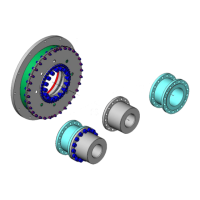
Measure the angular misalignment with a dial gauge (see Fig. 5-3).
Attach the dial gauge to the flange/hub/adapter (E/3/17).
Position the sensor of the dial gauge radially against flat surface at a
distance R.
Turn the flange/hub/adapter (E/3/17) with dial gauge and flywheel (B)
slowly by 360°.
The maximum dial gauge deflection must not exceed the value 2xS
w
at any
point. The permissible tolerance S
W max
should be taken from the table below.
Align the units (calculated deviation ≤∆K
W max
).
Permissible angular alignment tolerance:
∆K
W max
=0.05°
Table 5-2 Permissible angular alignment tolerance