leakage current and their manifestation methods are as follows:
(1) Leakage current to the ground: refers to the leakage current flowing through the common ground wire,
which not only flows into the inverter system but also may flow into other equipment through the
ground wire. These leakage currents may cause leakage circuit breakers, relays or other equipment to
malfunction;
(2) Leakage current between lines: refers to the leakage current flowing through the distributed capacitance
between the input and output cables of the inverter. The magnitude of the leakage current is related to
the carrier frequency of the inverter, the length of the motor cable, and the cross-sectional area of the
cable. The higher the carrier frequency of the inverter, the longer the motor cable, and the larger the
cross-sectional area of the cable, the greater the leakage current.
6.3.4 Power supply filtering
The filter can play a very good role in electromagnetic decoupling, even if the working conditions are met,
it is recommended that the user install it.
The installation method and precautions are as follows:
(1) The filter is installed between the motor and the frequency converter and between the power supply
and the frequency converter. The installation position should be close to the frequency converter, and
the length of the lead wire should be shortened as much as possible;
(2) Make sure that the filter shell is in good contact with the chassis shell, and connect the grounding wire;
(3) The input and output lines of the inverter filter should be kept apart, and parallel lines should not be
avoided, so as not to reduce the electrical performance of the inverter filter.
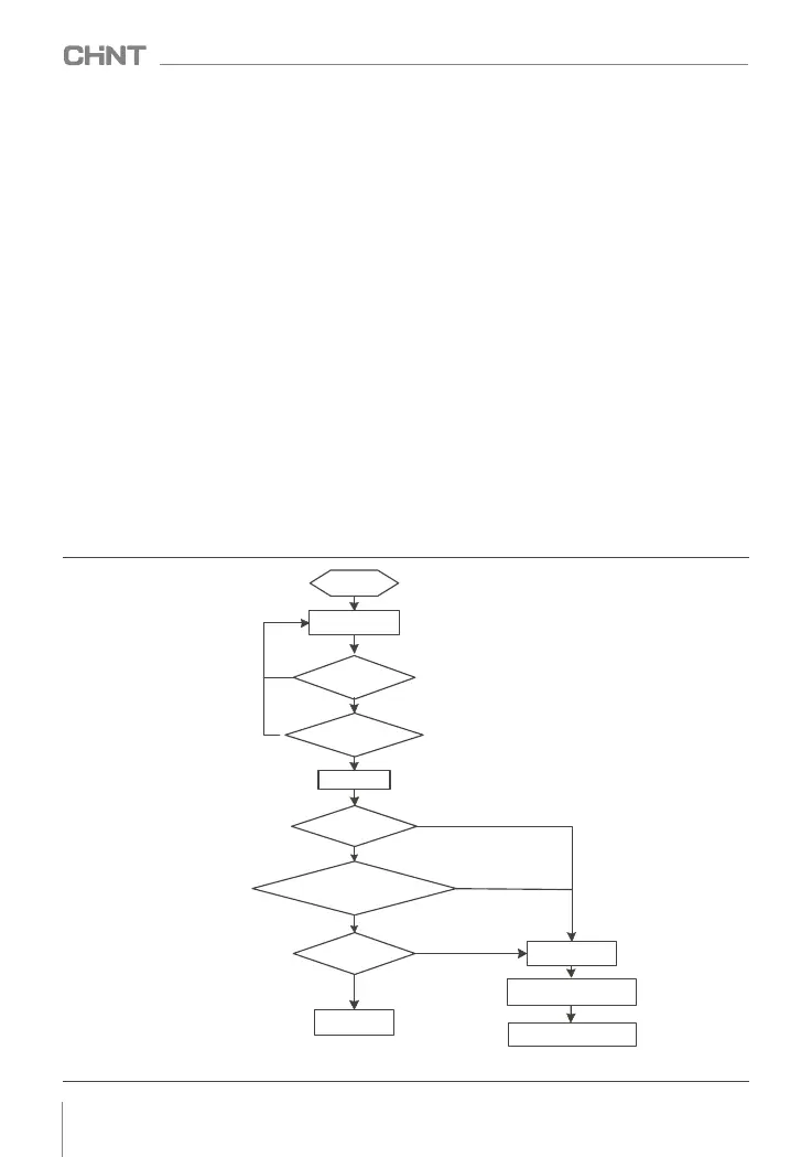
6.4 Power on for the first time
Please follow the technical requirements provided in this chapter for installation and wiring. The power-on
process is shown in Figure 6.1 :
Figure 6.1 Inverter power-on operation process
START
WIRING
Ensure that cables are correctly connected
by referring to Installation and Wiring
NO
CHECK WIRE
NO
CHECK INPUT VOLTAGE
POWER ON
YES
YES
First show 8.8.8.8.8, then
show then show O.FF
SCREEN LIGHTING
SOUND OF RELAY CLOSED
DEFAULT VALUE 50.00Hz
SHOW FREQUENCY
FAULT
TRIP THE BREAKER
RUNNING
CHECK THE FAILURE CAUSE
NO
NO
NO
YES
YES
YES
024
NVF2G-S Series Inverter User's Guide
 Loading...