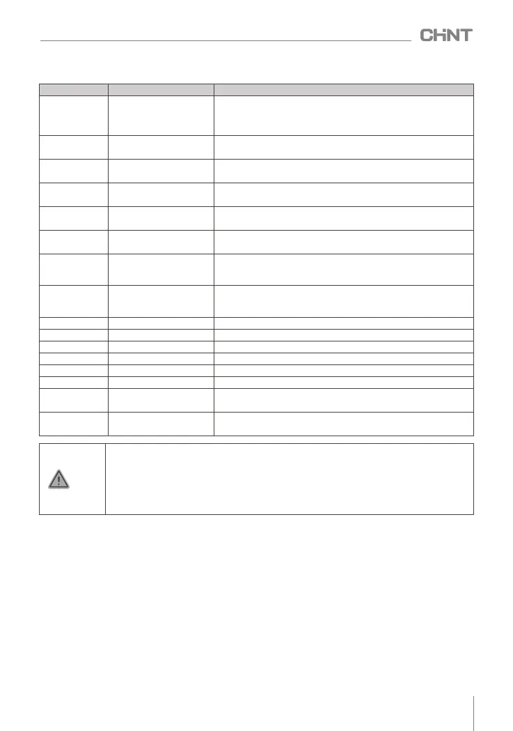
Table 4.5 Function description of control board terminals
1) Terminal COM is the common terminal of X1-X6 digital control signal (multi-function input terminal),
terminal GND is the common terminal of AI1 , AI2 , AO1, AO2 terminals, please do not connect
them to the ground.
2) The wiring of the control circuit terminal should use shielded or twisted pair, and must be wired
separately from the main circuit and strong current circuit.
2
3) The control circuit is recommended to use 0.75 mm cables for wiring.
4) The control circuit cannot input strong electricity, otherwise the inverter will be damaged.
Notice
4.4 Instructions for use of control terminals
4.4.1 Multifunctional input terminal
COM is the common terminal of X1-X6, which can be a current source or a sink current. X1-X6 has flexible
external interface methods, and the typical wiring methods are as follows:
1) For source wiring, it is necessary to short 1-2 of J606. The specific wiring diagram is shown below.
Terminal mark Terminal name illustrate
R1A , R1B , R1C ,
R2A , R2B , R2C
Relay contact output
RA and RB are normally open contact groups, RB and RC are normally
closed contact groups, the function of RO 1 is set by parameter F6.02 ,
the factory default default output is fault output , and the function of
RO 2 is set by parameter F6.03 , the factory default has no function
Yl , COM
Open collector output
The function is set by parameter 6.01 , and the factory value is forward
rotation state signal output.
485+, 485-
serial communication
terminal
Terminal for RS485 serial communication with the outside .
+10V
Power supply for
frequency setting
And A I1 , AI2 , GND — potentiometer ( 4.7k Ω ~10k Ω ) .
Al1,GND
Analog signal input
terminal
Connect to potentiometer or 0V~10V signal as frequency setting , PID
setting or PID feedback.
AI2,GND
Analog signal input
terminal
Input 0V ~ 10V/0 (4) mA ~ 20mA signal as frequency setting, PID
setting or PID feedback.
AO1,GND
Analog signal output
terminal
Connect DC 0V - 10V/0 ( 4 ) mA ~ 20mA voltmeter between AO1 and
GND , which can be used to indicate operating frequency, output
current, output voltage, etc.
A 2, GNDO
Analog signal output
terminal
Connect a DC 0V~10V/0 ( 4 ) mA ~ 20mA voltmeter between AO2
and GND , which can be used to indicate operating frequency , output
current, output voltage, etc.
X1
Multi-function input terminal 1
The factory setting is forward rotation
X2
Multi-function input terminal 2
The factory setting is reverse running
X3
Multi-function input terminal 3
The factory setting is run pause
X4
Multi-function input terminal 4
The factory setting is free parking
X5
Multi-function input terminal 5
The factory setting is no function
X6
Multifunctional input terminal six
The factory setting is no function
COM
Multi-function input terminal
common ground
Common land of X1~X6 , use with X1~X6
24V,COM
Auxiliary power supply
24V output
DC power supply 24V output ( ≤ 50mA )
015
NVF2G-S Series Inverter User's Guide
 Loading...