EasyManuals Logo

CHINT NVF2G-S Series User Manual

CHINT NVF2G-S Series
115 pages
To Next Page IconTo Next Page
To Previous Page IconTo Previous Page
Page #24 background imageLoading...
Page #24 background image
Signal
Outside Controller
VFD
33
22
11
J606
Signal
VFD
Outside Controller
Figure 4.15 PNP type wiring diagram
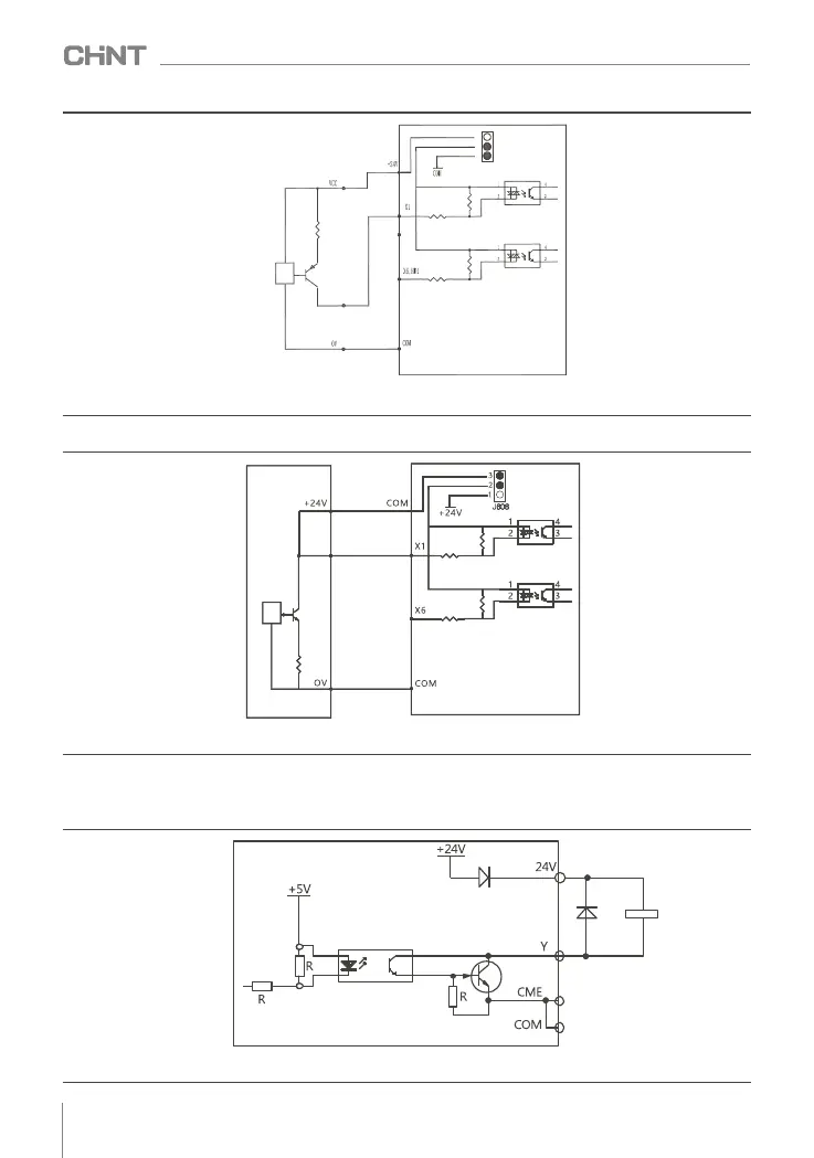
   2) Sink wiring needs to short-circuit 2 - 3 of J606 . The specific wiring diagram is shown below.
4.4.2 Multi-function output terminal
   (1) The multifunctional output terminal Y1 can use the +24V power supply inside the inverter, and the
wiring method is shown in Figure 4.17.
Figure 4.16 NPN type wiring diagram
Relay
VFD
Figure 4.17 Multi-function output terminal wiring mode 1
016
NVF2G-S Series Inverter User's Guide
HDI

Table of Contents

Questions and Answers:

Question and Answer IconNeed help?

Do you have a question about the CHINT NVF2G-S Series and is the answer not in the manual?

CHINT NVF2G-S Series Specifications

General IconGeneral
BrandCHINT
ModelNVF2G-S Series
CategoryInverter
LanguageEnglish

Related product manuals