Relay
VFD
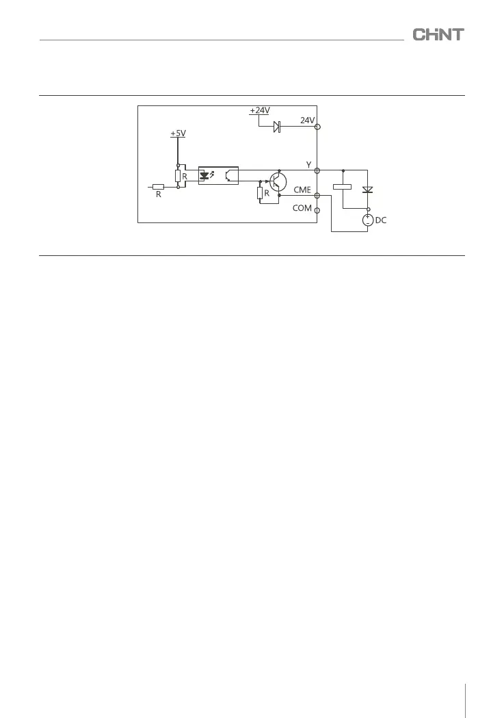
(2) The multi-function output terminal Y1 can also use an external power supply, and the wiring method is
shown in Figure 4.18.
4.4.3 Relay output terminals RIA, RIB, R1C, R2A, R2B, R2C
If driving inductive loads (such as electromagnetic relays, contactors), a surge voltage absorption circuit
should be installed, such as: RC absorption circuit (note that its leakage current should be less than the holding
current of the controlled contactor or relay), varistor, Or freewheeling diodes, etc. (used in DC electromagnetic
circuits, be sure to pay attention to polarity when installing). The components of the absorbing circuit should be
installed at both ends of the coil of the relay or contactor.
Figure 4.18 Multi-function output terminal wiring mode 2
017
NVF2G-S Series Inverter User's Guide
 Loading...