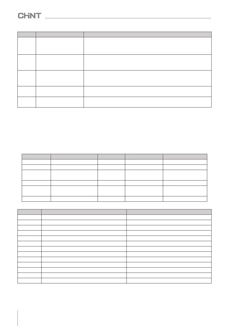
set value
Function
illustrate
29
Output current exceeded
After the output current of the inverter exceeds the output current limit value
of F8.22, and the duration exceeds the output current limit detection delay
time F8.23 , DO outputs a valid signal ; output current limit value = F8.22 ×
F 2.03 (motor rated current) .
31
Motor overload pre-alarm
Before the motor overload protection action, judge according to the overload
early warning coefficient FE.03, and output a valid signal after exceeding the
pre-alarm threshold.
34
arrive on time
When the timing function selection F8.32 is valid, the inverter will output a
valid signal after the current running time reaches the set timing time, and
the timing time is set by F8.33.
35
AI1 > AI2
When the value of analog input AI1 is greater than the input value of AI2, a
valid signal is output.
37
The current running time is
reached
When the accumulative running time of the inverter exceeds the time set by
F8.34 current running arrival time, it will output a valid signal.
note: Serial numbers not listed in the table are "reserved"
8.11.3 Analog input terminal function (AI)
NVF2G-S series inverters are equipped with 2 analog input terminals AI1 and AI2 as standard, both of which
support 0V ~ +10V, 4mA ~ 20mA command input, and the voltage and current can be realized through the
"jumper switch" on the control board. switch. For the method used by the AI channel, please refer to "2.11.4
Setting the main frequency through the analog signal".
8.11.4 Analog output terminal function (AO)
NVF2G-S series inverters are equipped with 2 analog output terminals AO as standard.
AO terminal function selection details are as follows:
note: Serial numbers not listed in the table are "reserved".
8.12 Instantaneous power failure continuous operation function (instantaneous power failure non-stop function)
The non-stop function after instantaneous power failure enables the system to continue to operate during
short-term power failures.
.
function code
name
default value
Predetermined area
Parameter Description
F 6.08
AO1 output function selection
0 0 ~ 36
F6.09
AO2 output function selection
0 0 ~ 36
F6.12
AO1 zero offset correction
coefficient
0.0%
(-100.0 ~ 100.0)%
F6.13
AO1 gain
1.00 -10.0. ~ 1 0 . 00
F6.14
AO2 zero offset correction
coefficient
0.0%
(-100.0 ~ 100.0)%
F6.15
AO 2 gain
1.00 -10.0. ~ 1 0 . 00
set value
Function
illustrate
0
no function
1
operating frequency
2
set frequency
3
Set frequency (after acceleration and deceleration)
4
output speed
5
Output current
6
output current 2
7
Output torque (absolute value)
8
Output Power
9
The output voltage
10
bus voltage
11
AI1
12
Ai2
no function
0 ~ maximum output frequency
0 ~ maximum output frequency
0 ~ maximum output frequency
0 ~ maximum speed
0 to 2 times the rated current of the inverter
0 to 2 times the rated current of the motor
0 to 3 times the rated torque of the motor
0 to 2 times the rated power of the motor
0 ~ 1.2 times the rated voltage of the inverter
( 0.0 ~1000.0) V
(0 ~ 10)V
(0 ~ 10)V
060
NVF2G-S Series Inverter User's Guide
 Loading...