9
RS485-MODBUS communication instructions
9.1 Networking method
The inverter provides RS485 communication interface, and adopts the international standard Modbus
communication protocol for master-slave communication. Users can realize centralized control through PC/PLC ,
host computer monitoring software, etc. (setting inverter control commands, operating frequency, modification
of relevant function code parameters, monitoring of inverter working status and fault information, etc.), to
adapt to specific application requirements.
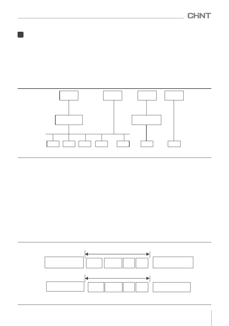
As shown in Figure 9-1-1 , there are two networking modes of the inverter (as a slave station): single-master
/ multi - slave mode, single-master / single - slave mode.
Main engine
( PC )
Main engine
( PLC )
Main engine
( PC )
Main engine
( PLC )
RS485
RS232
Conversion module
RS232/RS485
RS485
Inverter Inverter
RS485
RS232
Conversion module
RS232/RS485
InverterInverterInverterInverterInverter
...
Figure 9- 1 -1 Schematic diagram of inverter networking mode
9.2 Interface
RS485 interface: asynchronous, half-duplex. Default: 8-N-1 ( 8 data bits, no parity, 1 stop bit), 9600bps ,
RTU , slave address 0x01 . For parameter setting, see the function code description of Group Fb .
9.3 communication method
1) The communication protocol of the inverter is Modbus protocol, which supports RTU and ASCII protocols.
2) The frequency converter is a slave machine, master-slave point-to-point communication. When the
master uses the broadcast address to send commands, the slave does not respond.
3) In the case of multi-machine communication or long-distance, connecting the positive and negative
terminals of the signal line of the master station in parallel ( 100-120 ) ohm resistance can improve the
anti-interference performance of the communication.
4) The inverter only provides RS485 interface. If the communication port of the external device is RS232 ,
an additional RS232/RS485 conversion device is required.
9.4 protocol format
The Modbus protocol supports both RTU mode and ASCII mode, and the corresponding frame format is
shown in Figure 3-4-1.
Start
(at least 3.5 characters
free)
Start
(0x3A)
RTU Mode
Modbus data frames
Slave
address
Command
code
Data
Check
code
Slave
address
Command
code
Data
Check
code
Start
(at least 3.5 characters
free)
End
(0x0D, frame tail byte)
ASCII Mode
Modbus data frames
Figure 9- 4 -1 Modbus protocol format
065
NVF2G-S Series Inverter User's Guide
 Loading...