Wherein, the check code is a CRC check value.
9.4.2 ASCII mode
In ASCII mode, the frame head is "0x3A" , and the frame tail is "0x0D , 0x0A" by default , and the frame
tail can also be set by user configuration. In this mode, except for the frame header and frame tail, the rest of
the data bytes are all sent in ASCII code, the high 4 -byte group is sent first, and then the low 4 -byte group is
sent. The data in ASCII mode is 7 bits long. For "A" ~ "F" , use the ASCII code of the uppercase letters . At this
time, the data is verified by LRC , and the verification covers the information part from the slave address to the
data. The checksum is equal to the complement of all the characters involved in the checksum (discarding the
carry bit).
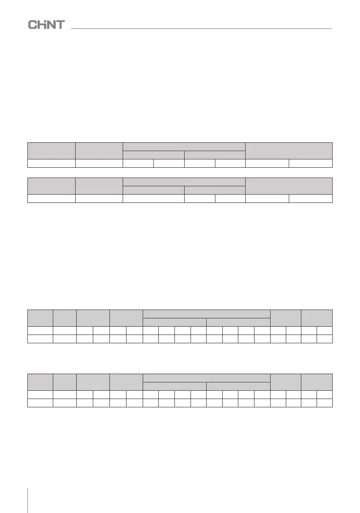
The following example is used to write 4000 ( 0xFA0 ) to internal register 0201 (F 2.01 ) of slave 5 in ASCII
mode.
Request frame:
9.4.1 RTU mode
In RTU mode, the idle time between frames takes the larger value between the function code setting and
the Modbus internal agreed value. The minimum inter-frame idle time agreed within Modbus is as follows: the
frame header and frame tail define the frame through the bus idle time not less than 3.5 bytes. The data
verification adopts CRC-16 , the whole information participates in the verification, and the high and low bytes
of the checksum need to be exchanged before sending. For specific CRC checks, please refer to the examples
at the end of the protocol. It is worth noting that it is enough to keep at least 3.5 characters of bus idle between
frames, and the bus idle between frames does not need to accumulate the start and end idle.
The following example is used to read the parameters of the internal register 0x 0101 (F1.01) of slave No.5
in RTU mode.
Request frame:
Response frame:
slave address command code
data
check code
register address
read word count
0x05
0x03
0x01 0x01
0x00
0x01
0xD5
0xB2
0x05
0x03 0x02 0x00 0X00 0x49 0x84
slave address command code
data
check code
response bytes
Register content
Among them, the check code is the LRC checksum, and its value is equal to the complement of ( 05+06+
02+01+0x0F+0xA0 ).
Response frame:
frame
header
Slave
address
command
code
data
check
code
end of
frame
register address
write content
character
:
0
5
0 6 0
2
0
1
0
F
A 0 4 3 CR LF
ASCII 3A 30
35
30 36 30 32 30
31
30 46
41
30 34 33 0D 0A
The inverter can set different response delays through function codes to meet the specific application needs
of various master stations. The actual response delay for RTU mode is not less than 3.5 character intervals, and
the actual response delay for ASCII mode is not less than 1ms .
9.5 Protocol application
9.5 .1 Modbus command code
The main function of Modbus is to read / write the function parameters of the inverter, and different
command codes determine different operation requests. The Modbus protocol of the inverter supports the
operations in Table 3.1 below.
frame
header
Slave
address
command
code
data
check
code
end of
frame
register address
write content
character
:
0
5
0 6 0
2
0
1
0
F
A 0 4 3 CR LF
ASCII 3A 30
35
30 36 30 32 30
31
30 46
41
30 34 33 0D 0A
066
NVF2G-S Series Inverter User's Guide
 Loading...