A.5 leakage protector
Since there are electrostatic capacitances to the ground inside the inverter, inside the motor, and the input
and output leads, and the carrier wave used by the inverter is relatively high, the leakage current of the inverter
to the ground is relatively large, especially for large-capacity models, which sometimes causes the protection
circuit to be damaged. Misoperation. When encountering the above problems, in addition to appropriately
reducing the carrier frequency and shortening the lead wires, a leakage protector should also be installed. The
leakage protector should be installed on the input side of the inverter. The operating current of the leakage
protector should be greater than that of the line under industrial frequency power supply. When the frequency
converter is not used, the leakage current is 10 times the sum of the leakage current of the line, noise filter,
motor, etc.
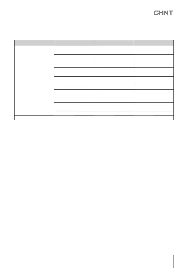
Table A.4 Braking resistor table
1.5
400
250
2.2
250 250
3.7
150
400
5.5
100
500
7.5
75
800
11
50
1000
15
40
1500
18.5
30 4000
22
20 4000
30
10
6000
37
16
9000
45
13.6
9000
55
10 12000
75
6.8
18000
90 6.8
18000
110*
6
18000
Voltage (V)
Motor power(kW)
Resistance value(Ω)
Resistance power (W)
(380~440)V
*Including 110/PS4, excluding 110/TS4 products
087
NVF2G-S Series Inverter User's Guide
A.4 Braking resistor table
The braking resistor selection of the inverter is shown in Table A.4 :
 Loading...