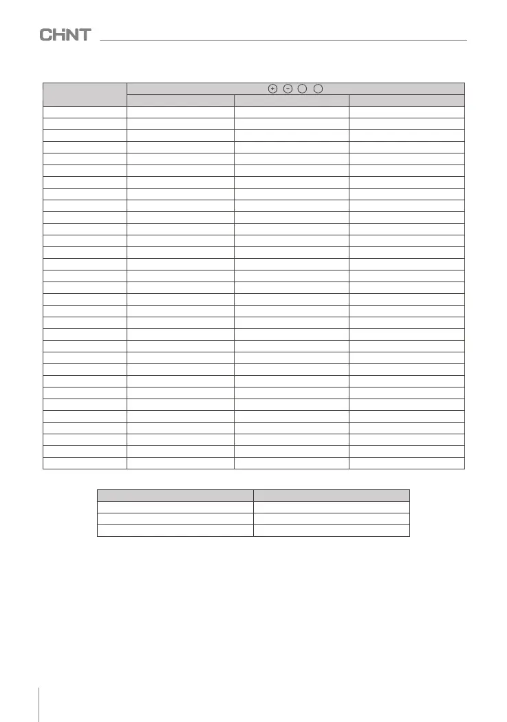
Table 4.2 Main circuit terminal wiring and installation torque
Inverter model
terminal screw
Tightening torque (N·m)
2
Wire specification (mm )
NVF2G-S-1.5/P(T)S4
M4
1.2~1.5
2.5
NVF2G-S-2.2/P(T)S4
M4
1.2~1.5
2.5
NVF2G-S-3.7/P(T)S4
M4
1.2~1.5
4
NVF2G-S-5.5/P(T)S4
M4
1.2~1.5
6
NVF2G-S-7.5/P(T)S4
M4
1.2~1.5
6
NVF2G-S-11/PS4
M4
1.2~1.5
6
NVF2G-S-11/TS4
M5
2.5~3.0
6
NVF2G-S-15/P(T)S4
M5
2.5~3.0
6
NVF2G-S-18.5/P(T)S4
M5
2.5~3.0
10
NVF2G-S-22/PS4
M5
2.5~3.0
16
NVF2G-S-22/TS4
M8
9.0~10.0 16
NVF2G-S-30/P(T)S4
M8
9.0~10.0
25
NVF2G-S-37/(T)PS4
M8
9.0~10.0
25
NVF2G-S-45/P(T)S4
M8
9.0~10.0
35
NVF2G-S-55/P(T)S4
M8
9.0~10.0
50
NVF2G-S-75/P(T)S4
M8
9.0~10.0
60
NVF2G-S-90/P(T)S4
M8
9.0~10.0
70
NVF2G-S-110/PS4
M8
9.0~10.0 100
NVF2G-S-110/TS4
M10
17.6~22.5
100
NVF2G-S-132/P(T)S4
M10
17.6~22.5 150
NVF2G-S-160/PS4
M10
17.6~22.5 185
NVF2G-S-160/TS4
M12
31.4~39.5 185
NVF2G-S-185/P(T)S4
M12
31.4~39.5 185
NVF2G-S-200/P(T)S4
M12
31.4~39.5
240
NVF2G-S-220/PS4
M12
31.4~39.5 150×2
NVF2G-S-220/TS4
M16
85.2~90.4
150×2
NVF2G-S-245/P(T)S4
M16
85.2~90.4
150×2
NVF2G-S-280/P(T)S4
M16
85.2~90.4
185×2
NVF2G-S-315/P(T)S4
M16
85.2~90.4 250×2
NVF2G-S-355/P(T)S4
M16
85.2~90.4 325×2
NVF2G-S-400/P(T)S4
M16
85.2~90.4 325×2
R, S , T , , , , , U, V, W
+1 +2
Table 4.3 Grounding Wire Standards
Cross-sectional area of power cord
Cross-sectional area of grounding
S ≤ 16
S
16<S ≤ 35
16
35<S
S/2
4.3 Description of control circuit terminals
4.3.1 Control terminal and wiring diagram
012
NVF2G-S Series Inverter User's Guide
 Loading...