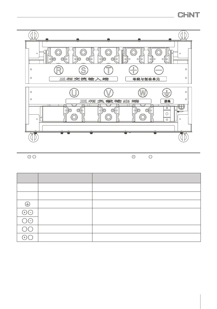
Figure 4.11 Main circuit terminal NVF2G-S-315/TS4~400/TS4
Note : , DC bus positive and negative terminals ; if braking is required, external braking resistors are connected
between .
Table 4.1 Main circuit terminal description table
Terminal s
ymbol
Terminal name
Functional description
R , S , T
Main circuit power input
Three-phase AC input terminal, connected to the power grid
U , V , W
Inverter output
Three- phase AC output , generally connected to the motor
Ground terminal
The safety protection ground terminal P E must be reliably grounded
Connection terminals for DC bus
or external brake components
As a DC bus connection or an external brake component connection
terminal, it needs to be connected according to actual needs
DC reactor connection terminal
For external DC reactor, please remove the short circuit when
connecting DC reactor
External braking resistor
connection terminal
When it is applied to the connection terminal of an external braking
resistor, connect it according to actual needs
+1
B
+1 +2
011
NVF2G-S Series Inverter User's Guide
 Loading...